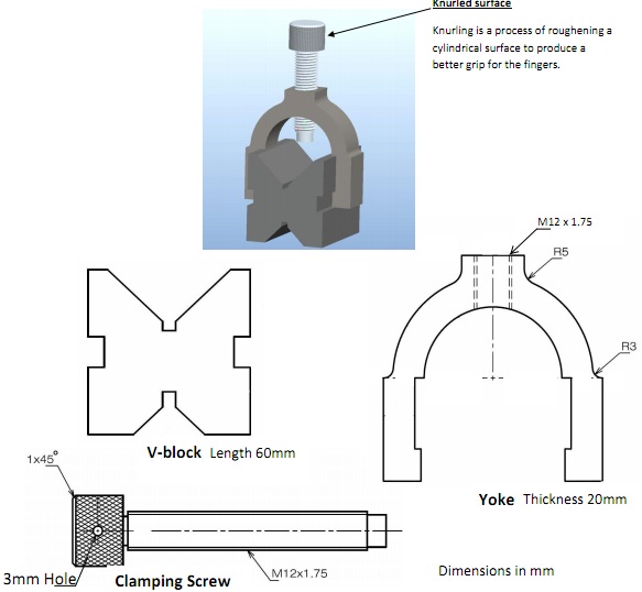
V-block and clamp:
The V-block clamp comprises of 3 components, a V-block, yoke and clamping screw. By using a rule, measure the sketches below and produce a third angle projection drawing for each component. All drawings should be fully dimensioned, with the relevant projection symbol, on a completed drawing sheet.
Point out any important tolerances for each component.
The completed two view assembly drawing is as well needed showing each component in its relevant position, with information bubbles associating to a parts list on the drawing. The parts list must point out, part name, page number, material, and number off, for each component.
Finally on a separate sheet generate a free hand sketch of the completed assembly.
Do not forget to attach the standard coversheet.