Assessment Task:
You are required to submit via electronic MyCourse/Turnitin upload, a single technical report of a professional standard to satisfy the following requirements.
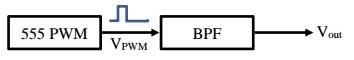
A company has given you the task to design, simulate and breadboard a 555-timer based pulse-width modulation circuit with subsequent filter stage to the following specification:
Frequency:
The 555-timer circuit needs to produce a signal of frequency f = xy kHz where xy are the last two digits of your student ID (if it is ‘00’, the frequency shall be 80 kHz).
Duty Cycle:
The duty cycle is to be designed such that it is D = (90-xy)/2 % (e.g. for xy=‘48’ the duty cycle would be (90-48)/2 = 42/2 = 21%). The duty cycle must be a minimum of 5% though, i.e. if D = (90-xy)/2 is smaller than 5%, use D = 5%.
Filter stage:
The output of this PWM signal generator then requires filtering. For this purpose, use the second-order cascaded bandpass filter shown in figure. It is made of a combination of a low-pass filter stage followed by a high-pass filter stage. You are required to calculate suitable component values for R and C such that the above PWM frequency (of ‘xy’) is selected as the centre frequency of the bandpass, thus being the cut-off frequency of each of the filter stages, i.e. use equal values for RL = RH as well as CL = CH. The gain of the second stage is required to be 10 (i.e. R'H = 10 x RH)
Design, then simulate, then implement (breadboard) the full circuit. Marks are given for adetailed description of the design and calculation procedure, using circuit diagrams, showing component values and the signals (oscilloscope plots and spectrum analyser plots) for the voltage across the PWM capacitor, VC the PWM output signal, VPWM and the final filtered signal, Vout Simulation plots, oscilloscope screenshots and photos of the working breadboard are required for full marks.
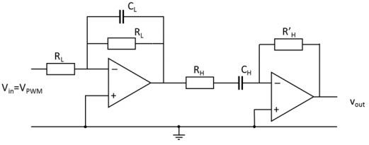
Figure: The filter stage required to filter the output signal. Component values will have to be determined based on the filter frequency.