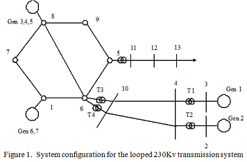
Problem: The topology of the 14-bus system this project is based upon is shown in Figure. This figure represents a diagram of an Arizona looped 230kV transmission system. This is a typical system configuration for serving a large city. Figure is the single line diagram of the 230kV and 345kV systems that shows the series impedance values. (Per unit values shown in Figure use an MVA base of 100 MVA, and voltage bases of 230kV and 345kV at appropriate places within the system.) Notice that remote generation is input to the loop via two 345kV lines. The voltage is transformed from 345kV to 230kV by three-phase transformer banks T3 and T4. Transformers T1 and T2 step the voltage up at the remote generating site. The transformer data for this system follows:
Transformers:
Transformers 1 and 2 are 3-phase rated at 350 MVA, 22kV delta to 345kV grounded wye, 8% reactance; Transformers 3 and 4 are 3 phase rated at 400 MVA, 345 kV grounded wye to 230 kV grounded wye, 6% reactance.
Most of the tutors of our Three-Phase Transformer Assignment Help service are equipped with Masters and Ph.D. credentials in the relevant field and are capable enough to write on any topic of any complexity level. We are at your doorstep; all you have to do is to approach us!
Tags: Three-Phase Transformer Assignment Help, Three-Phase Transformer Homework Help, Three-Phase Transformer Coursework, Three-Phase Transformer Solved Assignments