--%>

Problem on displacement response time history

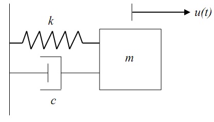
(i) Formulate the equation of motion for the system shown in Figure below. List two assumptions made in this formulation.

(ii) Find the response of this system at t = 3s. The system begins with the displacement of 5 cm and velocity of 3 cm/s. Given that m = 300 kg, k = 5 kN/m and c = 150 Ns/m. Draw the displacement response time history.

1596_displacement response.jpg

   Related Questions in Mechanical Engineering

  • Q : What is Cotter joint Cotter joint :

    Cotter joint: These kinds of joints are employed to connect two rods that are under compressive or tensile stress. The ends of rods are in the way of a socket and shaft which fit altogether and the cotter is driven into a slot which is common to both

  • Q : Servo drive What do you mean by Servo

    What do you mean by Servo drive and how mechatronic integration approach is improved by it.

  • Q : Diesel Engine What will happen if the

    What will happen if the gasoline is used within the Diesel Engine, whether the Siesel Engine will work or not?

  • Q : Hard links Explain the term hard links?

    Explain the term hard links?

  • Q : Maintenance in Product design

    Maintenance: How frequently and easily the product is to be maintained must be specified. A photocopier shouldn't require a service call from a technician just to add toner. If the product is to be maintenance free, then costs may be increased due to

  • Q : Problem on magnitude of force A

    A horizontal pipe of dimension 540 mm diameter carrying 0.6 m3/s splits into two horizontal pipes of 300 mm diameter with 60% of the flow and another of 150 mm diameter with 40% of the flow. Find out the magnitude and direction of the force

  • Q : Gasoline in Diesel Engine If the

    If the gasoline is used in the Diesel engine explain whether the Diesel engine will work?

  • Q : Problem related to the value of the

    Water flows via a pipe of about 300 mm diameter at the rate of 66 L/s. Evaluate the value of the manometer reading, ‘h’. The Specific gravity of manometer liquid is taken as 0.8.  

  • Q : Describe Process Flow Diagram Process

    Process Flow Diagram: A Process Flow Diagram or System Flow Diagram exhibits the relationships among the main components in the system. It too has fundamental information regarding the material balance for the process.

  • Q : Life expectancy in Product design

    Life expectancy: This part of the specification will state how long the product should remain in working order provided the customer gives reasonable care and maintenance. Also take into account technological advances and ongoing improvements that wou