Details: The task is all about a design project that requires the use of the program creo, no coding require. Just engineering drawings and some calculations and some writing.
This is an individual exercise which involves the design of the mechanical parts of a variable pitch propeller.
Statement of Requirements:
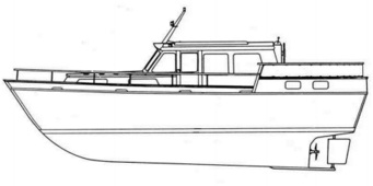
1. A generic work boat, Figure Typical Boat is to be propeller driven through a nominal 2:1 (2.051 actual) reduction gearbox.
2. In order to obviate the need to provide a reversing gear and a clutch, the pitch of the propeller blades is to be variable. Thus by changing the angle of the propeller blades the boat can be made to move forwards, backwards or remain stationary.
3. The target minimum forward design speed in still water is 10 knots and in reverse 6 knots.
4. The propeller drive shaft is enclosed in a stern-tube and extends forward into the boat from the rear of the keel, which is welded into the hull just forward of the propeller.
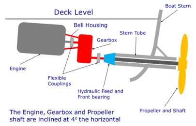
5. The propeller shaft is supported by two bearings at either end of the stern tube, 2.0m apart. One bearing capable of taking the thrust from the propeller is mounted in the stern-tube at the aft (rear) of the boat and the second bearing is a cylindrical roller bearing mounted at the front. This roller bearing has an inner race diameter of 65mm.
6. The overall diameter of the propeller shall not exceed 500 mm. In the interests of efficiency, the diameter of the hub should be as small as is consistent with providing a reliable working system.
7. As the craft will operate in shallow water there is significant probability of total fouling of the propeller or just one blade. In the event of total fouling with the throttle fully open, the engine will stall and the shock torque will reach 150% of its peak value. If one blade is fouled and the there is an attempt to vary the pitch the maximum actuation force will be taken by that one blade and its attachment. In either event no parts, other than the blades, will suffer permanent set or damage.
8. The Company have spent a great deal of time and money on developing a blade and the associated manufacturing process. It has an efficiency of 70%. This blade will be used on a range of propellers and it is a non negotiable requirement that it is used on this design, Propeller Blade Forging. The base wil be machined to suit but the blade profile must not be changed.
9. It is expected that the forward/reverse selection will be connected with throttle operation so that the craft may be controlled by a single lever, which does not form part of this design.
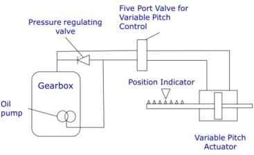
10. The pitch control is to be actuated using an existing hydraulic source from a gear pump; the pressure regulating valve is set at 200 bar, Figure Hydraulic Circuit.
11. The maximum angle of attack for the propeller is 30 degrees pitch for forward movement and since the boat is not required to travel quickly in reverse 15 degrees.
12. The force required to activate the propeller is a function of the hydrodynamic and mechanical design of the blades. Experience has shown that, with the available pressure, a piston minimum effective area of 1650mm2
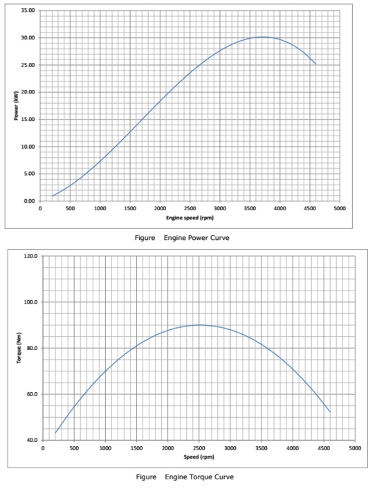
13. The engine chosen for the first application is a four cylinder 2 litre diesel. The engine parameters are shown in Figure Engine Power Curve and Figure Engine Torque Curve. The Specific Fuel Consumption is 0.264 kg/kWh at maximum power.
14. The propeller has been carefully optimised and excessive speed will lead to significant inefficiency. There is an electronic limiter on the engine which can be adjusted to any speed less than the maximum rating of the engine. This will be used to ensure the propeller shaft speed is limited to 1300 rpm +/-2 5%.
15. Hydraulic fluid is directed to the propeller by two concentric tubes. One for forward pitch and the other for reverse pitch, there is design freedom of choice which does which, see Figure 6 Front Bearing Arrangement. These tubes rotate with the propeller shaft.
16. The central oil tube, the smaller one, has an additional function. It is connected at the servo-valve to indicate the pitch sense and magnitude see Figure Hydraulic Circuit. Therefore it must be capable of axial movement and be connected to the hydraulic piston in the pitch change mechanism, only the part in the propeller needs be designed, ignore the servo connection.
17. The total transmission system will experience major (zero to max power), minor (random throttle movements) cycle loads and high cycle vibration. These varying loads can be accumulated into ‘equivalent’ major cycles. There is knowledge within the Company that if parts are designed for a minimum life of 10000, 0 to max major cycles that provides a satisfactory product.
18. Bearings shall have an L10 Life of 10000hrs
19. The first whirling speed of the drive shaft shall be at least 120% of the maximum speed. (Consider only the part of the shaft between the bearings, ignore the overhung mass).
20. When operating in shallow water the propeller will stir up mud and sand from the bottom. Reliability is of paramount importance and it must not be possible for the propeller to be lost nor for the bearings to be damaged by contaminants.
21. The annual production will be 5000 units.
22. The propeller arrangement shall remain water and oil tight at all conditions; all joints shall have suitable sealing.
23. As the unit is directly in contact with sea water consideration shall be given to the choice of materials and/or corrosion protection.
Deliverables:
Design the hub, the variable pitch mechanism, the propeller shaft; select the rear bearing and seals. Investigate the suitability of the standard blade with the hub using Momentum Theory
A short report is required which should contain the following paragraphs:
1. An introduction 150 words
2. An executive report max one side of A4 describing the rationale for the chosen design configuration and justification for the selected standard machine elements such as bearings, seals and fasteners, illustrations may be used in his paragraph additional to the one side of A4 but suitably annotated.
3. A clear presentation of all calculations. (This may be in spread sheet form if presented in the same way as the given, spread sheet plus MS Word definition)
4. In a separate paragraph answers to the following questions:
- What is the final calculated speed of the boat (as opposed to the
- What is the percentage difference in area actual/ideal
- What is the reserve factor for the Ultimate stress on the shaft?
- What is the reserve factor for Fatigue stress on the shaft?
- What is the first whirl speed of the oil tubes?
- A recommendation (no design) of what needs to be done, if anything,
- What is the calculated bearing life in hours?
- What is the maximum drag force (kN) of a boat to achieve the calculated speed.
- What is the total weight of the design, neglect the stern tube and hydraulic tubes? Consider only 100.0mm of propeller shaft forward of
- the rear bearing.
5. A General Arrangement drawing of the Variable Pitch Propeller. This should clearly show how the operating mechanism, the rear bearing and seals are assembled together using appropriate sectional views and notes. Specify necessary fits.
6. A Detail drawing of the piston. You need to specify all necessary dimensions and tolerances so that the part may be costed for manufacture.