--%>

Undamped single degree of freedom

(a) The response for an undamped single degree of freedom system under free vibration is given as where ωn is the natural frequency and A and B are unknown that can be determined from the initial conditions. The response  can also be written as where φ is the phase angle.

Prove that C and φ are:

2071_single degree.jpg

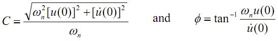
where u(0) and ú (0) are the initial displacement and velocity, correspondingly

(b) Plot the solution given  in part (a) for the case k = 1000 N/m and m = 10 kg for two complete periods for all the following sets of initial situations

(i) u(0) = 0,  ú (0) = 1 m/s
(ii) u(0) = 0.01 m, ú (0) = 0
(iii) u(0) = 0.01 m, ú (0) = 1 m/s
 
(c) Make a three-dimensional surface plot of the amplitude C of an undamped oscillator given in part (a) versus u(0) and ú (0) for the range of initial conditions given by -1 ≤ u(0) ≤ 0.1 m and -1 ≤ ú (0) ≤ 1 m/s for a system with natural frequency of 10 rad/s. Based on the plot, determine the initial conditions that give the maximum and minimum amplitudes.

   Related Questions in Mechanical Engineering

  • Q : What is pneumatic system Pneumatic

    Pneumatic system is a system which employs air to power something. For illustration, have you seen the tube systems at the bank drive-up tellers? Air is employed to push the tubes back and forth from the teller to customer.

    Q : Servo drive What do you mean by Servo

    What do you mean by Servo drive and how mechatronic integration approach is improved by it.

  • Q : Stop cooling-water flow in turbine

    Whether you stop cooling-water flow through steam condenser when the turbine is slopped?

  • Q : Working environment in Product design

    Working environment: The conditions under which the product is likely to be used, stored, and transported must be specified. The product may have to operate in conditions of extreme temperature, be subject to vibration, radiation; these conditions wil

  • Q : Describe Process Flow Diagram Process

    Process Flow Diagram: A Process Flow Diagram or System Flow Diagram exhibits the relationships among the main components in the system. It too has fundamental information regarding the material balance for the process.

  • Q : Problem on motion of the system (a) A

    (a) A plane moving at a constant velocity, V, crashes into a building as shown in figure below. Due to the design against plane crash of that building, neither major damage nor explosion occurs but the building vibrates after the crash. Assuming that the building can

  • Q : Problem related to mass flow rate Water

    Water flows via a control volume as illustrated in the figure below. At Section (1) the diameter is 40 mm and the velocity profile is given by the V(r) = 10 (4 – r2) m/s, here r is the  distance from the centerline. At Section (2) the mass flow r

  • Q : Free Vibration of MDOF Systems Why free

    Why free vibration takes place at MDOF system?

  • Q : Problem on head loss The pump

    The pump illustrated in the figure adds 20 kW of power to the flowing water. The only vital loss is that which takes place across the filter at the inlet of the pump. Find out the head loss for this filter. Note that the gage pressure upstream of the filter is negativ

  • Q : Powder Technology Explain the term

    Explain the term Powder Technology?