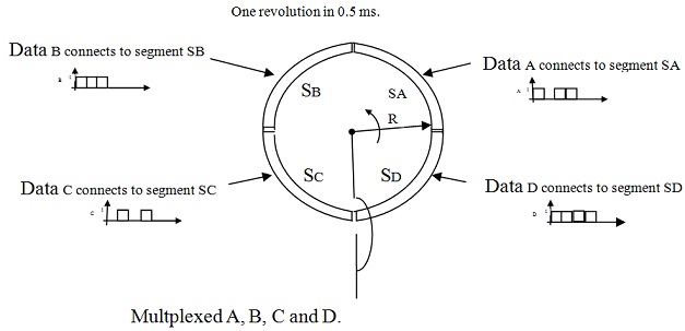
Q1. The figure shows a commutator diagram to explain the time division multiplexing. Draw the multiplexed signal over the range 0 to 1 ms labeling the axis and state all the relevant data rates.
Q2. A sine wave signal of amplitude 10 V is fed to a transmission line where it was noted that the sine wave of amplitude 1.5 V was reflected from load. Find out the reflection coefficient. Based on this computation explain how the power transferred all along a transmission line can be quantified and how data are influenced by reflection.
Q3. The given signal is measured on the data communication channel if no data signal is applied. Describe the importance of this by using the relevant communication concepts.