Question 1: Describe the independent and dependent sources with the help of V-I characteristics.
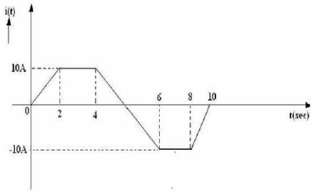
Question 2: A pure inductance of 3 mH carries a current of the wave form shown in figure. Find out the voltage across Inductor VL(t) and sketch the same.
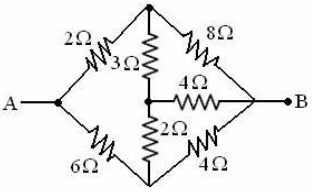
Question 3: Find out the resistance between the terminals ‘A-B’ in the network shown in below figure.
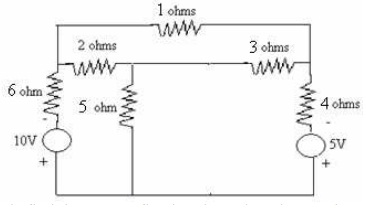
Question 4: By using loop analysis find out the current flowing via 5 ohms resistor.
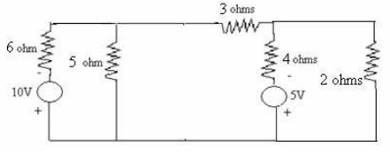
Question 5: By using nodal analysis find the current flowing through 3 ohms resistor.
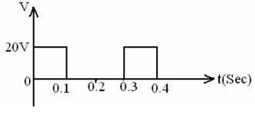
Question 6: Calculate the RMS and average values of square wave form shown in figure below.
Question 7: A series circuit consisting of a 10 ohms resistor, a 100 µF capacitance and 10 mH inductance is driven by a 50 Hz AC voltage source of maximum value 100 V. Calculate the equivalent impedance, current in the circuit.
Question 8: A parallel circuit having two branches, first branch consisting of 3 ohms resistor is in series with 12.7 mH inductor, second branch consisting of 1 ohm resistor in series with 3.18 mH is connected across 200 V, single phase, 50 Hz supply.
Calculate:
a) The resultant admittance.
b) Total current input.
c) The current in each branch.
Question 9: A voltage V = 50 ?00 V is applied to a series circuit consisting of fixed inductive reactance XL = 5 ohms and a variable resistance R. Sketch the admittance and current locus diagrams.
Question 10: A series RLC circuit has to be designed so that it has a band width of 320 Hz and inductance of the coil is 0.2H. It is has to resonate at 350Hz, determine the resistance of coil and capacitance of condenser. If the applied voltage is 150V, determine the voltage across capacitor and coil.