Solve the below problem:
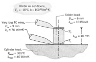
Q: The thermocouple (TC) installation on a snowmobile engine cylinder head is shown in the schematic. The TC wire leads are attached to the upper and lower surfaces of the cylindrically shaped solder bead. The base of the bead is attached to the cylinder head operating at 385°C, and there is a thermal resistance between the bead and the cylinder head due to the constriction of heat flow from the head to the bead. This constriction resistance may be expressed as Rcon = 1 / (2khead D sol). The TC wire leads are very long and experience heat loss to the winter air at - 10°C with a convection coefficient of 100 W/m2 · K. Values of other geometrical and thermal parameters are shown on the schematic.
The objective of this problem is to develop a thermal model that can be used to determine the temperature difference (T1 - T2) between the two intermediate-metal TC junctions. Assume that the solder bead does not experience any heat loss from its lateral surface.
(a) Sketch a thermal circuit of the installation labeling temperatures, thermal resistances, and heat rates. Write expressions for each of the thermal resistances and calculate their values.
(b) Use your thermal circuit to evaluate (T1 - T2) for the prescribed conditions. Comment on the assumptions made in building your model