Question 1:
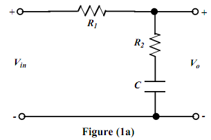
(a) Figure (1a) shows an electric-circuit which is called a phase-lag network. Derive the transfer function, i.e. G(s) = Vo(s)/Vin(S) for the network. Show all your working.
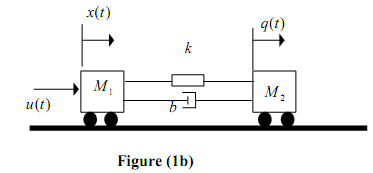
Two carts with negligible rolling friction are connected as shown in Figure (1b). An input force u(t) is applied. The masses of the two carts are M1 and M2 and their displacements are x(t) and q(t), respectively. The carts are connected by a spring k and a damper . b
Answer the following questions:
(b) By using Newton's Second Law, derive two mathematical equations that describe the motion of the two carts.
(c) Hence derive the transfer function that relates the displacement q(t) and the input u(t), i.e. G(s) = Q(s)/U(s).
Question 2:
A system with unity feedback is shown in figure (2).
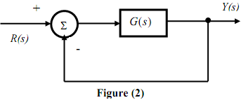
Given that G(s) = 4/s(s+3) determine the closed-loop response (i.e. ) (t y ) of the system when R(s) = 1/s.
Question 3:
(a) Simplify and determine Y(s)/ R(s) for the block diagram of figure (3). Use block-diagram reduction methods.
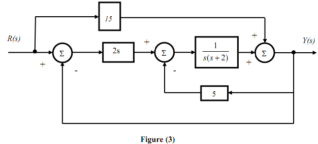
(b) Consider the above bock-diagram of figure (3). You are now required to derive the transfer function Y(s)/R(s), by using the signal flow graph method. Label in your working, the paths and loops associated with the block-diagram.