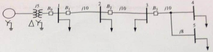
Consider radial system shown in fig which represents a portion of a larger system. Bulk power is fed from a substation represented by the source on the left.
Assumptions:
i) The source is an infinite bus; the voltage on the low (right) side of the transformer is 34.5 kV (line-line).
ii) Prefault currents are negligible compared with fault currents, The reliant voltage profile is flat.
iii) The model shows actual impedances in ohms positive; positive-, negative-, and zero-sequence impedances are assumed equal. Resistances are neglected.
iv) The transformer impedance is j5 referred to the 34.5 kV side.
v) Faults may occur anywhere to the right B1. Faults may be solid 3-phase. single-line to-ground (S-L-G), line-to-line (L-L), and double-line-to-ground (D-L-G). Assume a solid fault (that is, Z = 0).
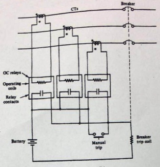
vi) For each breaker there are three overcurrent relays (one for each phase). A three-phase breaker should be tripped if a fault condition is detected on any phase. A schematic of the setup is shown in Fig. Note that the breaker trip circuit is activated if any overcurrent relay operates.
The objective is to pick CTs and relay settings to protect the lines and buses 2, 3, 4, and 5. Also, B2 should back up B3 and B1 should back up B2. Suppose that the coordination time delay is specified to be 0.3 sec.
1. Consider a 3-phase solid fault just to the right of B3.
(a) Determine the voltage at the buses.
(b) Determine the line currents.
2. Consider a 3-phase solid fault to the right of B2.
(a) Determine the voltage at the buses.
(b) Determine the lint currents.
3. Consider a L-I, fault at bus 4 (say between buses h and c).
(a) Determine the voltage at the buses.
(b) Determine the line currents.
A) Select CT ratio and relay setting of R1 associated with breaker B1.
B) Select CT ratio and relay setting of R2 associated with breaker B2.
C) Select CT ratio and relay setting of R3 associated with breaker B3.
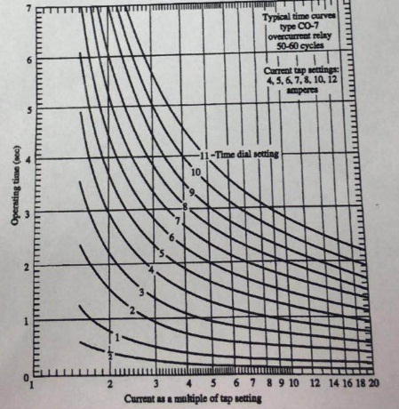
The fig shows the characteristics of CO-7 Time-delay overcurrent Relay.