Assignment: Isolation and Fault Detection for Lateral Flight of an UAV
Introduction:
Fault tolerance is very significant for aircraft flight control. The majority of the faults take place in the actuators and sensors onboard the aircraft. Once a fault has occurred the aircraft could become uncontrollable and be hazardous to passengers and crew. This assignment is to examine the effects of sensor faults on the lateral dynamics of an Unmanned Aerial Vehicle.
Background
Lateral Dynamics
The Lateral Dynamics of any aircraft are defined in terms of the Body-fixed velocities and corresponding Earth-fixed orientation (see Figure).
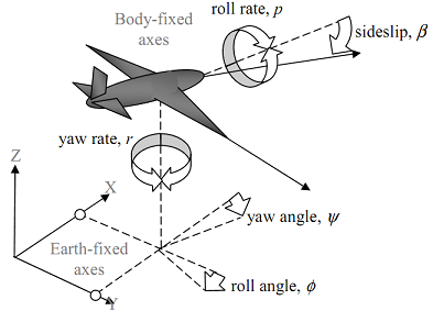
In this specific case the velocities are roll rate (p) and yaw rate (r). All other Body-fixed dynamics are regarded as constant (e.g. surge velocity) or zero. The effects of such velocities on to the initially fixed Earth-fixed axes are represented through the orientation of the aircraft.
These are the roll angle (φ) and yaw angle (ψ). In addition, the affect of sideslip on the aircraft is included in the form of the sideslip angle (β).
The corresponding inputs to the lateral dynamics of the aircraft are the aileron deflection (δa) and the rudder deflection (δr). The ailerons control the roll motion and the rudder controls the heading or yaw. The Lateral Dynamics of an UAV can be represented by the following differential equations:
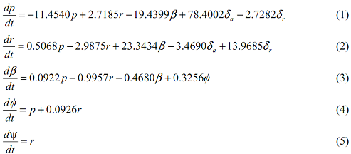
Here the translational velocities are calculated in m/s, rotational velocities in rad/s and the angles in radians. The constant value for the surge velocity is taken to be U0 = 30 m/s.
In addition to the flight dynamics, this aircraft representation also consists of the dynamics of the aileron and rudder actuators. Both actuators have a maximum amplitude deflection of 25 degrees and a maximum rate limit of 5 degrees/second.
Faults in Lateral Dynamics
The faults in the Lateral Dynamics of an aircraft can be either multiplicative or additive. The multiplicative faults occur in the dynamics of the aircraft and can be caused by changes to the aircraft itself throughout flight. These types of faults are not considered here. Instead, additive faults caused by the sensors in the system will be the main focus of this assignment. In particular faults which occur on the heading channel which are added to the sensed dynamics from the aircraft shall be the subject of this study.
Problem Specification
The following stages are expected to be performed in this assignment:
Question1. Construct a continuous time simulation of the Lateral Dynamics of the UAV using zero initial conditions.
Question2. Simulate a suitable man oeuvre where changes in heading can be observed (e.g. zig-zag).
Question3. Simulate three separate stepwise faults in the heading channel of magnitudes 2, 5 and 10 degrees.
Question4. Simulate a separate drift wise fault in the heading channel.
Question5. Analyses the effect of these separate faults.
Question6. Using a suitable limit checking method, detect these faults in the system.
Question7. Using a suitable fault diagnosis method, diagnose these faults.
Question8. Repeat this investigation with simulated white noise of amplitude ±5degree included in the heading output of the system.
Question9. Explain how the FDI system has to be altered to accommodate the existence of noise.
Question10. Comment on the influence of the faults and the FDI system on the Lateral Dynamics if a heading control system was employed.