House Burglar Alarm Specification
A house has 2 rooms each of which have PIR motion sensor. Each room has the security light. There is also a PIR sensor outside front door that becomes active when it is dark outside. There is a security light outside the front door. Security lights are switched on, and an audible alarm sounds under certain conditions.
If the outside PIR is triggered (that is, it is dark, and motion is detected), the outside security light is switched on for 20 seconds. Any room sensor activated will trigger the light for (only) that room for 10 seconds. Both room sensors activated within 10 seconds will set off the audible alarm continuously.
Only way to stop audible alarm is to input the correct PIN. If correct PIN is input, the alarm system is de-activated, and becomes dormant (ready for further burglar detections). If incorrect PIN is entered, a ‘first warning’ is given on an LCD panel.
If the further incorrect code is entered, the alarm remains on, the outside light flashes, and a message is sent to the police station. Entering the correct code at any time that the audible alarm is on will de-activate the alarm.
The STD shown in first Figure is intended to reflect this requirement specification. Second figure below shows the hardware to be used for the implememntation and testing of the code.
Tasks for the specification given:
1) Produce a Flowchart
2) Produce a working program
a) uses sensible labels in code, and is easy to read
b) uses correct inputs
c) generates correct LED outputs
d) generates correct LCD outputs
3) Produce report, presenting all above, readable to software/hardware engineer
4) A demonstration of the working program.
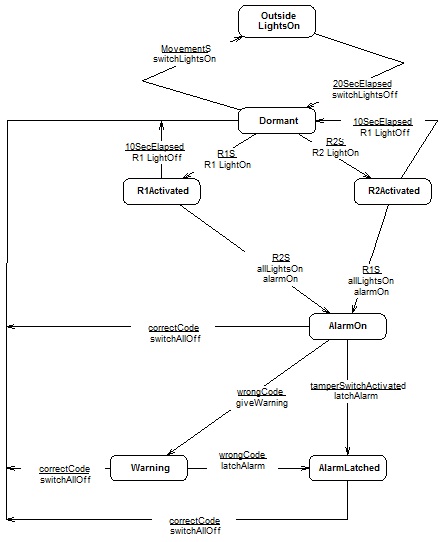
Figure State Transition Diagram for Simple Burglar Alarm
Key:
inputs:
• R1S => room1 sensor, simulated on hardware by switch on RB0 active.
• R2S => room2 sensor, simulated on hardware by switch on RA5 active.
• MovementS =>movement sensor, simulated on hardware by analogue input on RA3 >= half full scale.
• CorrectCode simulates correct PIN input, simulated by RB0 active.
• WrongCode simulates incorrect PIN input, simulated by RA5 active.
• tamperSwitchActivated, simulated by analogue input on RA3 < half full-scale.
outputs:
• LED D8 indicates Dormant state. D1 indicates R1Activated state. D2 indicates R2Activated state.
• D3 indicates AlarmOn state. D4 indicates Warning state. D5 indicates AlarmLatched state.
• D6 indicates OutsideLightsOn state. D7 may be used for any purpose. The LCD should indicate the state in words.
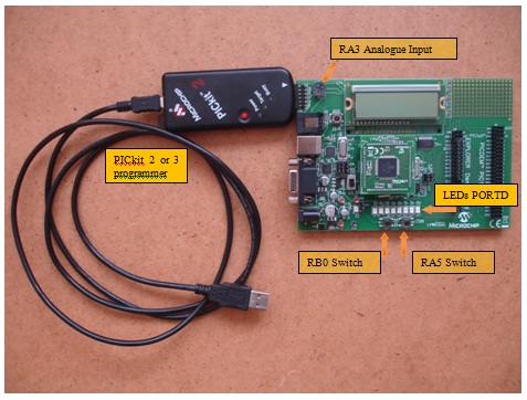
Figure Hardware for implementation and testing of the program