Assignment: Analog Measurements
Review the explanation of a wind vane described later:
You are to create an assembly program for the MSP430 which correctly measures the wind direction, to a precision of 45° (N, NW, W, SW, S, SE, E, NE), using the MSP430’s ADC.
Your program will output the direction by using four LEDs, one each for N, S, E and W. If the wind direction is out of the N, only the N LED will light. When the wind direction is out of the NW, both the N and W LEDs with be ON.
Note that the actual circuit interfacing to the wind vane will employ the 3.6V supply on the Launch-pad board itself. This signifies that voltage readings given in the table require to be appropriately scaled. As per the table, a 10kohm resistor will be employed in the voltage divider.
As just one wind vane is available for use, test your code by using a pot connected between ground and 3.6 V (the supply voltage for your board). The wind vane will be accessible in 310 for final check-out. Pots, LEDs, and resistors will be given in 310.
Your program should use at least one subroutine. You are free to select which functionality to place in the subroutine.
Extra Credit:
1) Properly measure all the 16 directions possible by the vane. Develop some method for visually displaying the added directions.
2) Store the voltages corresponding to the particular directions as constants in a memory array (see illustration below). Have your code cycle via this array until a match is found.
ORG 0xD000
DC 0x1234, 0xABCD, … ;replace w/ calculated voltages
Deliverables:
• Pseudo code for your algorithm.
• Short description in words of how program works.
• Commented source code, see below.
• Soft copy, emailed to instructor, of your code.
Comments:
• Comment your code at a level of detail sufficient for someone to follow it. More detail than that is not helpful.
• Comprise several comments lines at the very top of your program which explains the program, what it does, who wrote it, when it was written, what hardware it needs, and what inputs/outputs it uses. This is termed as a header.
; Example program for demonstrating header section does nothing
; Targets MSP430G2231 on LaunchPad board
; Stephen Craven, ENEE 4700, 9/23/2010
; Program does what?
; Input is ... Output is... BE SPECIFIC. Include enough info for
; Someone to configure and use your program.
Wind Vane:
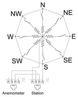
The wind vane is the most complicated of the three sensors. It has eight switches, each joined to a different resistor. The vane’s magnet might close two switches at once, allowing up to 16 different positions to be indicated. The external resistor can be employed to form a voltage divider, producing a voltage output which can be measured with an analog to digital converter, as illustrated below.
The switch and resistor arrangement is shown in the diagram.
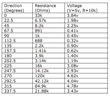
Resistance values for all the 16 possible positions are given in the table.
Resistance values for positions between those shown in the diagram are the result of two adjacent resistors connected in parallel when the vane’s magnet activates two switches simultaneously.
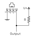
Example: wind vane interface circuit. Voltage readings for a 5 volt supply and a resistor value of 10k ohms are given in the table.