Assignment:
Question 1
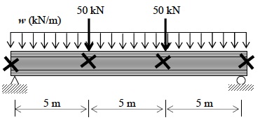
Design the beam shown below for the strength and serviceability limit state according to ASwo and AS4100. The concentrated live loads acting on the beam are shown in the Figure below. It supports nominal uniformly distributed dead and live loading of 25 kN/m and 20 kN/m respectively. The beam is laterally supported at the load and reaction points.
Question 2
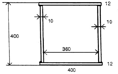
Prove that the welded box section shown below is non-compact and determine the design section strength for bending about the horizontal centroidal axis. Take fy = 360 MPa.
Question 3
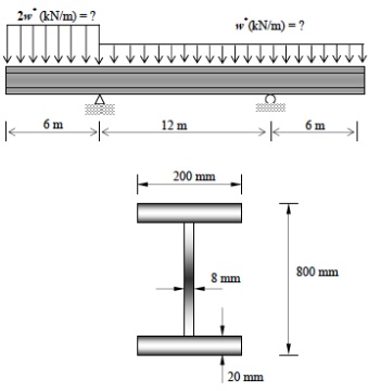
The figure below shows an overhanging beam. The section geometry is given in the same figure. The beam is restrained laterally and from twist during buckling at the supports only, and the loads are applied at the level of the top flange. Determine:
(i) The design value of w' to cause lateral buckling of the beam in aocordanoe with AS4100.
(ii) Check the adequacy of the beam web in shear at the design value of w' calculated in (1). Design intermediate web stiffeners if required.
(iii) Check whether load-bearing stiffeners are necessary at the supports. (Stiff bearing plate length at supports = 300 mm.)
Question 4
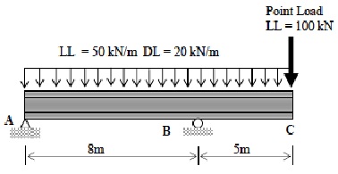
The statically determinate beam shown below carries the unfactored service loads as shown. There is a UDL applied to the top flange consisting of a live load of 50 kN/m kiiirtu and a dead load of 20 KN/m (excluding self-weight). There is also a concentrated live load of no kN applied on the top flange at the end C. The top and bottom flanges are laterally braced at points A, B and C.
Design a suitable compact plate web girder based on strength limit states. The section should be compact and the web should not require intermediate transverse stiffeners. The overall depth of the girder cannot exceed 1000 mm. check if load bearing stiffeners are required at the support and under the concentrated load. Design bearing stiffeners if required. The beam is supported on 250x250 mm bearing plates. Take fy = 300 MPa.
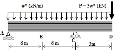
Question 5
The beam shown in the figure below carries a factored design uniformly distributed load w* (kN/m) and a concentrated load at D of P = 3w* both acting on the top flange. The beam is fully braced at points A, B, C and D. the cross section used for the beam is a 530UB82. Calculate the design load w* that be safely carried by this beam.