Experiment:
Optics
Objective: To examine how images can be formed from the light of distant sources.
Equipment: Example lens (magnifying, reading glasses, or eyeglasses for a farsighted person), a small hand mirror, blank paper; straight edge (ruler), protractor.
Description: Quantitative interpretation of astronomical images requires a knowledge of the relationship between the various points on the image and the corresponding celestial objects. This relationship follows from simple optical principles, i.e., the behavior of light in interaction with reflecting and refracting materials. Two important principles are used:
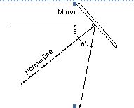
Law of Reflection: When light reflects from a smooth surface, the angle of incidence of a light ray is the same as the angle of reflection.
Law of Refraction: When light passes between a transparent media across a smooth boundary, the ratio of the sine of the angle of incidence to the sine of the angle of refraction is in the same ratio as the speed of light in the corresponding media. For lenses, this results in light rays initially parallel to each other bending toward or away from a focal point after passing through the lens.
For our purposes, there are several important consequences of the law of refraction:
Point 1) A lens bends ("refracts") all rays which pass through it with one exception: A ray passing through the center of the lens emerges from the lens in exactly the same direction as it was going when it entered. We say that a "central ray" is "undeviated" by its passage through the lens.
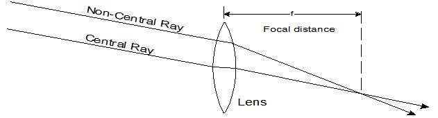
Point 2) Images of all distant objects (i.e., celestial objects) are formed in the "focal plane" of a converging lens. This plane lies at a fixed distance from the lens call the "focal length". Rays of light parallel to each other before entering the lens will converge at this focal plane.
Point 3) The angular size of an image is the same as the angular size of the object producing the image.
Procedure:
To show the properties of reflection, hold a small plane mirror perpendicular to a blank
Mark the line of the mirror on the paper, about in the middle of the paper. (If the mirror has a frame, try to mark the line where the actual reflecting surface lies. This is usually the back of a glass mirror.
Construct a line perpendicular "P" to the mirror line near one edge. Place a dark dot (the "object" "O") on that line about 5 cm from the mirror line. Holding the mirror on the mirror line, again perpendicular to the paper, use a pencil to mark where you see the image of the dot while looking in the mirror. This requires some dexterity, as the point is behind the mirror. You want to mark the spot where the point appears to be. Record the distance from the mirror to where you saw the image.
Now construct the image using the law of reflection: On your paper, draw a ray "R1" from your original dot to the line of the mirror, but not along the perpendicular, at an angle of about 30 degrees from the perpendicular to the mirror. Construct a "normal" line through the point where your ray "R1" meets the mirror, perpendicular to the mirror. Use the law of reflection to show where "R1" should be reflected by the mirror (see the figure above). Now project this reflection of ray "R1" through the line of the mirror to see where it intersects the line "P" behind the mirror. Do this again on the other side of line "P," but try to make your angle a bit different. Call this ray "R2." Ideally, the two projected rays and the line "P" will all intersect at the same point behind the mirror, called the image point, "I." Since we're using rather crude instruments, they probably won't, but they should be fairly close. If not, recheck your angle measurements.
A. How close is this image point "I1" (the intersection of "P" and "R1") from where you saw the image? (Give answer in millimeters). How close is "I2"?
One can show that the images in plane mirrors are the same distance behind as the object is in front. The image is called "virtual" because no real light comes from where you see the image.
If you get close to a concave mirror (also called a cosmetic mirror), your image will appear magnified. This again follows from the laws of reflection. Draw a segment of a circle "C" on a blank piece of paper with a large dinner plate as a template. Estimate the center of the circle (this won't be perfect, but try your best to make sure that the distance from the center to the edge is mostly the same all the way around your segment or circle). Draw a line "R" from the center to the middle of the segment of the circle you drew. Now put a short (about 4cm or so) line "L" perpendicular to R, about a quarter of the way from the center to the edge of the circle. "L" will act as the object we want to view in a curved mirror represented by "C". Construct four "rays", two from each end of "L", drawn toward the mirror "C" and then reflecting. To get the direction of the lines after reflection, use the law of reflection (angle of incidence to the normal is angle of reflection). The normal lines can be drawn for each of the four rays where they hit the mirror by drawing lines from the hit to the center of the circle. With the pairs of rays from each end of the line "R", see where the image forms.
B. Measure the radius of your circle segment.
C. Measure the distance of your line "L" from the circle "C" along line "R."
D. Measure how far your constructed image is from the mirror along line "R."
E. Is the image larger or smaller than the original object?
F. Is the image real or virtual?
G. How does your construction match what you observe in looking at a cosmetic mirror?
Clear glass in the shape of a lens (converging or diverging) also can produce images from the light of objects.
Hold a magnifying glass (or converging lens of an eyeglass) facing a distant light source (such as an electric lamp or a bright window). Hold a piece of blank paper on the opposite side of the glass. Move the paper toward or away from the glass until you can see a sharp image of the distant object.
H. Measure the distance between the lens and the paper and record. For very distant objects, this image distance is called the focal length of the lens. The inverse of this length (in meters) is what opticians call the "power" of the lens, measured in a unit called "diopters". This number appears on prescriptions for eyeglasses.
I. Calculate the "power" of this converging lens and record.
If you find two converging lenses (or different power eyeglasses), you can hold the stronger of the two near your eye and try to look through the weaker as you move it away from the first. If you are able to hold them so their separation is the sum of their focal lengths, you will have made a telescope, because distant objects seen through both lenses will appear magnified.