Assignment:
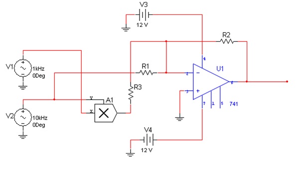
A third year engineering student is designing a modulating circuit in a simulator. The completed schematic is shown in Figure. When he simulates the output, the circuit seems to be working fully. He now takes a demodulating circuit which he has successfully designed and tested previously on a similar modulator and finds that he is getting distortion at the output. Component A1 represents a balanced modulator. The voltages for sources V1 and V2 have been measured with a multi-meter and are 2 and 3 rms V respectively. The carrier and message are both sinusoidal.
a. What type of modulation is he trying to perform? Motivate your answer.
b. Explain the operation of A1. Draw a block diagram to aid your explanation.
c. Draw the double-sided magnitude spectra of the signal at the output of the circuit (pin 6).
d. If the ratio of the power in the sidebands to the power in the carrier is four times that of the efficiency. Find the values for the resistors 1 R and 2 R and 3 R given that 2 R is two times 3 R and the square of 1 R is two times 3 R plus one.
e. If he has used the same demodulating circuit, what is the reason for the distortion at the output? How would you correct this?