1) Materials
a) Ecplain the general “four digit” system of designating aluminum alloys including modifiers
b) There are two types of aluminium alloy: 2024-T4 and 6061-T6511. Explain fully the meaning of the designations of these two specific cases. Make sure that your answers convey a basic understanding of the meaning of all technical terms used by briefly explaining any unfamiliar terms (e.g. don’t just write “artificially aged”). Cite all sources.
c) What is inconel? Describe, and give a present(within 20 years, say) example of a specific aerospace application of this material.
2)Loads Analysis
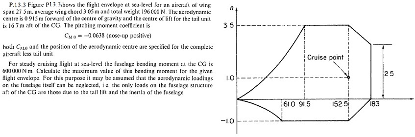
Complete the following problem from the text by Megson. Justify all work. Required, as part of your solution, show a free body diagram of half of the airplane cut through the C.G. appropriate for steady-level flight (where M=600,000 N-m is given) and a separate FBD of the complete aircraft for the maneuvering conditions (now M is unknown).
(Note: You must prove which point on the V-n diagram is critical. Also, show all necessary free body diagrams clearly. Also note that aerodynamic moments are considered in this problem.) Be careful with the scans below, as many decimal points have vanished.
3) Multiaxial Failure
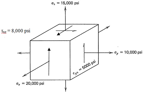
The aircraft flap actuator housing made of cast magnesium alloy ZAG3A-T4 with uniaxial yield strength σY = 14,000 psi. At the suspected critical point the calculated state of stress as shown in the figure.
a) Is yielding of this part expected according to the Maximum Shear Stress (Tresca) criterion? Justify your answer.
b) Is yielding of this part expected according to the Von Mises criterion? Justify your answer.
c) Compare the results of parts a and b and comment.
4) A cantilevered beam is to be made of 7075-T6 aluminum with a uniaxial yield strength of 469 MPa. The beam is 1m long, and is loaded with the following limit loads: a bending moment of 1 kN-m and an axial torque of 2 kN-m (these are applied simultaneously). Neglect stress concentrations at the wall [due to warping effects, in part b, the maximum torsion stress at the wall will be greater than that expected from simple mechanics of materials, but you may use the mechanics of materials approach here].
a) Assume a solid circular shaft is to be made of this material. Calculate the minimum diameter required to make sure that no yielding occurs at the limit load? Use the Von Mises criterion. Justify your work clearly. As part of your work, indicate clearly the x-y-z coordinate(s) of the critical point used in your analysis, and how this is determined.
b) Assume a solid square shaft is to be made of this material. Calculate the minimum side length required to make sure that no yielding occurs at the limit load? Use the Von Mises criterion. Justify your work clearly. As part of your work, indicate clearly the x-y-z coordinate(s) of the critical point used in your analysis, and how this is determined.
c) Compare the two cases and comment. Which of the two structures will be lighter? Also suggest alternate designs (still using aluminum) that may be lighter still (no calculations needed here, but justify/explain your reasoning).
5) Given: Brittle material has the ultimate tensile strength of 300 MPa and ultimate compressive strength of –1000MPa. Suppose that failure could be represented by Modified Mohr fracture criterion. Biaxial data show σi = –400 MPa.
a) Sketch, at least approximately to scale, the failure envelope for this material when loaded under biaxial stress (σx and σy exist, but all other components are zero.
b) Determine whether or not brittle failure is expected for each of the following biaxial stress states. Justify your work.
• σx = 500 MPa, σy = 100 MPa
• σx = 250 MPa, σy = –300 MPa
• σx = 250 MPa, σy = –700 MPa
c) Suppose the material is loaded in a biaxial tension-compression state where σx = 200MPa, σy = –C, C>0. Calculate maximum value of the C before brittle failure.
6) Failure of a composite Ply
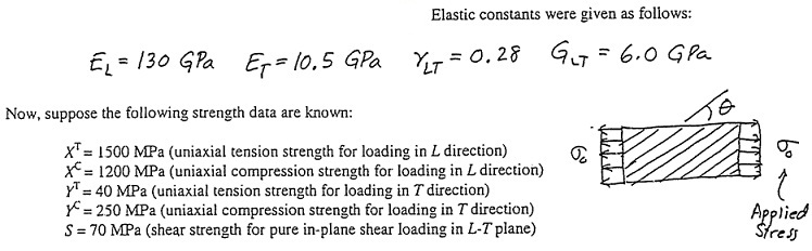
a) Calculate the value of σ0 to cause failure when θ=30°, according to maximum stress failure criterion. Consider both σ0 > 0 and σ0 < 0. Also, state nature of the expected failure modes for each case (e.g. “failure in longitudinal tension”).
b) Make a computer-generated plot of the failure stress σ0,ult as a function of θ for the range 0 < θ < 90°. Use the maximum stress failure criterion and assume σ0 > 0.
You can use MATLAB, Excel or any other package capable of making graphs.
Plot at least 90 data points, and connecting the computed values with straight lines. Do NOT use Excel’s “smooth curve” feature or similar functions. Also, turn off all “curve symbols” (the circles, squares, etc that identify individual computed points.
The only labeled numbers on the x-axis must be [0,15,30,45,60,75 and 90]