Transverse Shear Stress variation with changes in point load position
The aim of this experiment it to study the Transverse shear stress variations along the cross section of an I beam at the specified position. The loading condition will be varied and the corresponding shear stress distribution at the specified point will be evaluated and plotted as will be given in the procedure.
Procedure:
1. Without the load present, zero the digital force display.
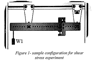
2. Apply point loads of
W1= on al= distance from left support
W2= on a2= distance from left support
3. Record the Shear Force (V) In Newtons
4. Repeat this exercise 3 times
5. For each loading plot the shear force variation diagram along x.
6. For the provided cross sectional area of the I beam calculate the Moment of Inertia, I about the centroidal z axis.
7. Determine Q factor at 3 the points shown below
8. Calculate the Transverse Shear Stress at the 3 points shown above using =
τ = VQ/It
Where V Is the shear force (N)
Q Is the q factor In mm3
I is the moment of inertia of the cross section about the centroidal axis in rnm° t, is the web or flange thickness in mm
9. Plot the Transverse shear stress distribution along this cross section.
10. REPEAT FOR ALL LOADING CONDITIONS.
Attachment:- 201408171350.pdf