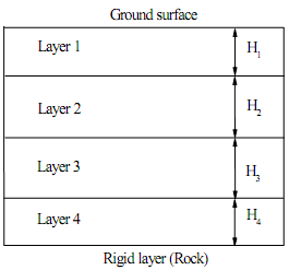
Figure 1 is the soil layer. Ground water table is at 5m depth. The thickness of each layer is determined by the "last" ID number. Four student numbers are used as the example. Based on this rule, Case 1 uses H1 = 8m, H2 = 5m, H3 = 1m, and H4 = 6m. Case 2 uses H1 = 6m, H2 = 1m, H3 = 5m, and H4 = 8m. Soil below Layer 4 is considered as a rigid stratum which can control failure mechanism.
Case 1
Layer 1: c' = 3kPa, φ' = 38°, and γ = 19kN/m3 (γsat = 20.3kN/m3)
Layer 2 : cu = 25kPa, c' = 8kPa, φ' = 25°, OCR = 2, Cc = 0.8, Cs = 0.16, e = 1.1 and γ = 15kN/m3(γsat = 16kN/m3)
Layer 3: c' = 0kPa, φ' = 38°, and γ = 18kN/m3(γsat = 19.1kN/m3)
Layer 4 : cu = 40kPa, φ' = 28°, OCR = 1, Cc = 0.5, e = 0.9 and γ = 16kN/m3(γsat = 17kN/m3)
Case 2
Layer 1 : cu = 30kPa, c' = 15kPa, φ' = 23°, OCR = 3.0, Cc = 0.8, Cs = 0.16, e = 1.1 and γ = 15kN/m3(γsat = 16.5kN/m3)
Layer 2: c' = 1kPa, φ' = 35°, and γ = 19kN/m3(γsat = 20.8kN/m3)
Layer 3 : cu = 35kPa, c' = 5kPa, φ' = 28°, OCR = 1.5, Cc = 0.5, e = 0.9 and γ = 16kN/m3(γsat = 17.3kN/m3)
Layer 4: c' = 0kPa, φ' = 35°, and γ = 18kN/m3(γsat = 19.1kN/m3)
Design the cut slopes for 12m height (Case 1) and for 7m height (Case 2), based on F = 1.3 (short-term), F = 1.5 (long-term) and F = 1.15 (seismic). There are only three options that can be used to increase F for the slope. They are, 1) reduce the slope angle;
2) reduce the slope height; and 3) dewater. The optimum design is the slope cut as less as possible. The water table change will induce the consolidation. The maximum vertical displacement due to dewatering on the slope crest must be less than 50mm.
Note:
- Both Circular and non-circular slip surfaces should be considered.
- The results from SLIDE must be shown to support your designs.
- After cutting, the reasonable long-term ground water profile can be considered using the assumption by Hoek-Bray charts (Slide 6 in week 9). However, the tension crack can be neglected.
- The location of drainage pipe must be shown as figure(s) if dewatering is used.
- The maximum consolidation settlement on the slope crest should be calculated and shown (it should be smaller than 50mm).
- If given information is not sufficient, rational assumptions can be made.