Problem 1: Figure 1 shows a large crawler crane in operation in a construction site.

Figure 1: Crawler crane
A) Sketch a 2D pin-jointed-structure model of the crane. You are allowed to make simplifications on the structure of the crane as you cannot be expected to figure out all the structural details from the photograph. You do not need to model the individual braces in the jib structure.
B) Indicate on your sketch the type of forces (e.g. tension or compression) that each member is subjected to when the crane is carrying a load.
C) Apply a statical determinacy test on your model. If it is not a determinate system, discuss what alterations can be done to make it statically determinate.
Problem 2:
A) Explain briefly why this structure in Figure 2 can be modelled as a pin-jointed structure (PJS) for the purpose of determining the axial forces in the members.
B) Show that the structure is statically determinate.
C) Determine the reaction forces at supports A and B.
D) Using the method of joints determine the axial forces in members AC and AF. You must show and clearly explain your working using appropriate free-body-diagrams.
E) Using the method of sections, determine the force in member GH. You must show and clearly explain your working using appropriate free-body-diagrams.
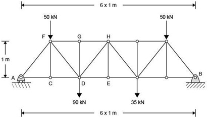
Figure 2: Truss structure
Problem 3: A composite is produced from a titanium alloy reinforced with aligned silicon carbide fibres. The elastic moduli of titanium and silicon carbide are 118 GPa and 380 GPa respectively. The composite contains approximately 50% titanium and 50% fibres.
A) Calculate the overall modulus of the composite, explaining your calculations and the assumptions you have made when it is loaded:
a. along the direction of fibre length
b. perpendicular to the fibre length.
B) Explain briefly why a material might show different yield behaviour in tension and compression when loaded cyclically.
C) A sample measuring 70 mm x 1 mm x 1 mm made from the composite is loaded to an applied stress of around 300 MPa along the longitudinal direction (the dimension measuring 70 mm).
The strains are measured:
in the titanium matrix: + 1300 μ∈ longitudinal; - 430 μ∈ transverse
in the SiC fibres: + 650μ∈ longitudinal; -75 μ∈ transverse.
Calculate the longitudinal and transverse stresses in the two phases from the measured strains (assume that the longitudinal and transverse strains are the principal strain components, and that the two transverse strain components are equal, i.e. ∈2 = ∈3). Take the values of Young's modulus and Poisson's ratio to be 118 GPa and 0.3 for the titanium, and 380 GPa and 0.18 for the SiC.
D) Describe two possible methods an engineer could use to predict if each of the phases was yielding. Mention the pros and cons for both methods.
Problem 4:
Note: For tackling parts of this Problem, you will need to use the 'K calculator' spreadsheet on the module website or the DVD.
A) A novel steel composite is being tested to determine its toughness. Compact tension samples are fatigue cracked and then loaded to failure. Three samples have been tested as shown in Table 1.
|
Sample
|
W / mm
|
B / mm
|
a / mm
|
Load at failure P / kN
|
|
|
|
|
|
|
1
|
50
|
5
|
24.9
|
6.2
|
|
2
|
50
|
20
|
25.1
|
28.1
|
|
3
|
50
|
30
|
24.6
|
42.5
|
a. Use the 'Compact tension specimen' geometry in the 'K-calculator' spreadsheet to calculate the value of K at failure for the three samples.
b. In order for a valid fracture toughness value to be obtained, both the sample thickness B and the final crack length, a, should satisfy:
B,a 2.5 ≥ (KQ/σyield)2
where KQ is the estimated toughness value of K at failure, and σyield is the yield strength of the material, which in this case is 700 MPa.
Calculate whether the samples are sufficiently thick (i.e. whether B is large enough) to meet this criterion. Are the final crack lengths acceptable?
B) A cylindrical pressure vessel of 2 m radius and 0.05 m wall thickness is manufactured from a steel with σyield of 700 MPa and fracture toughness of 90 MPa √m. The internal pressure of the vessel during operation is expected to reach 0.75 MPa. Before the component is installed, a non-destructive testing (NDT) contractor reveals a flaw of depth 17 mm.
i. Assess if the component is safe to be used. Use the 'Plate in tension - through- thickness edge crack' geometry in the K-calculator. You will need to calculate the hoop stress in the wall of the pressure vessel, assuming it to be a thin-walled cylinder.
ii. A safety-conscious engineer orders the flaw to be repaired. After repairing, NDT reveals that welding has introduced a new flaw, 6 mm in depth. It is assumed that as a result of welding, the residual stress in the region of the flaw is close to the yield strength of the steel. Will the vessel be safe to use in this situation? Explain how you come to your conclusion.
iii. Careful weld simulation reveals that in the region of the flaw, the residual stress is actually only 25% of the yield stress. Is the flaw safe under these conditions?
C) The safety engineer wants to purchase some new NDT equipment to detect flaws. Considering the stress conditions described in part (c): If a flaw must be detected before it grows to half the critical length, which of the devices given in Table 2 would be suitable? Explain your answer.
Attachment:- Statical Determinacy Test.rar