Assignment:
7-segment Display : Specification
Design and simulate a combinational logic circuit that controls a seven-segment display. Use the display device that is available in Logisim's Input/Output library. It accepts 8 logic signals as input, and it drives individual display segments ON or OFF based on these signals. With the appropriate input levels. recognizable (decimal) numbers will appear on the display. as illustrated in Figure 1.
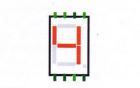
Figure 1. Example of a 7-segment display showing the numeral
Although this device is called a '7-segment display: it actually contains 8 segments if we count the small dot (period) at the lower right. More information about this device is provided in Logisim's documentation: With Logisim running, click Help → Library Reference → Input/Output Library → 7-segment display.
The input to your circuit will be 4 binary signals named I3, I2, I1 and I0 These signals will represent the binary encoding of a number in the range 0 to 9 (decimal), with 10 representing the least significant bit. These signals should cause the display to appear as indicated in Table 1. Note that 16 unique combinations are possible for these 4 inputs, but only 10 different numbers should be displayed. For the last 6 input combinations, as shown in the table, your circuit should cause the dot on the device to illuminate instead of showing a numerical value. The dot segment must be OFF for all other input combinations
Figure 2 illustrates a possible circuit layout structure for your design. The input signals r3, 12. i, and 1 C should be implemented within Logisim as "input pins". which are available near Logisim's top toolbar. These input pins are shown at the upper left of the figure. and the user can interactively turn these signals ON and OFF using the mouse. If the proper connections are in place when Logisim is running, signals with logic level 1 appear in green, and signals with logic level 0 are shown in black.
Table 1. Required state of the display device as a function of input signals 13 - :3 The period ('.') should be ON for input values 1010 through 1111 only.
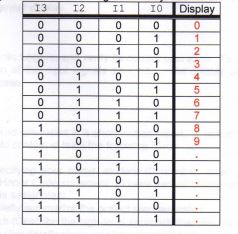
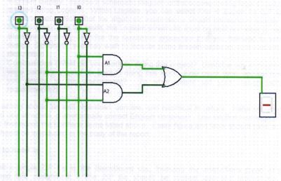
Figure 2. Logisim example with 4 inputs and a single connection to a 7-segment display device. Logic 1 levels are shown in green. This particular example shows both inputs to AND gate Al at level 1, and the output of this gate is therefore at level 1 also. This causes the output of the OR gate to be 1. which in turn drives a single horizontal segment of the display ON. (Please note that this example logic circuit is for illustration purposes only. Your design will undoubtedly need a different circuit to control the display segment that is illuminated. Your design will also need additional signals to control the other display segments.)
Your answer must be typed, double-spaced, Times New Roman font (size 12), one-inch margins on all sides, APA format.