Question1.
A pressure vessel is to be treated to generate compressive residual stresses on it inner surface. This involves increasing the pressure until taking 75% of the wall thickness goes into the plastic range. The external diameter of the vessel is 250mm and the internal diameter is 120mm, so that it must be regarded as a thick cylinder. The yield stress of the material is approximately 400MPa.
(a) Calculate the internal pressure required
(i) to cause first yield
(ii) to cause yield one third of the way through the wall thickness
(iii) to cause yield all the way across the wall
(b) Sketch a curve of internal pressure versus radius of yielded zone boundary for the cylinder. Comment on the factor of safety against plastic collapse associated with the target amount of yield, taking into account the assumptions inherent in the calculations.
Question2.
As part of the fitting of the mooring lines to a wave energy device, the pin-jointed structure shown in Figure is to be subjected to a small degree of plastic deformation by applying a force, F, in the direction shown. The structure is made from two members, each of cross-sectional area 50mm2, using a high strength steel whose elastic-plastic stress-strain relationship is
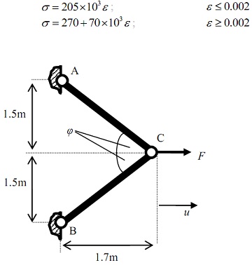
(a) Calculate the load, F, required causing first yield in members AC and BC.
(b) Find the deflection, u, for a load, F, of 35kN and determine the residual plastic strain in the members after removal of the load.
Question3.
A lifting shackle in a glass-making factory is made from a special high-temperature stainless steel. It is expected that the shackle will experience a tensile load of 5kN and the design allows for a maximum creep strain of 1% over the design life of 10,000 operating hours. The supplier of the alloy has measured the stress exponent, n, to be 4.5, the activation energy, QC , to be 110,000 J/mol and the pre-exponential constant, K2 , to be 2 ×10⁻⁸ (the constants K2 and n are in MPa, % and hour units).
(a) Calculate the minimum required cross-sectional area of the shackle if operating at 800oC.
(b) If the temperature were to be increased to 900oC and the load and cross-sectional area kept the same, what would be the time to 1% strain what would the creep strain be after 10,000 hours?
Question4.
A new high temperature alloy has been developed with creep properties as follows: stress exponent, m = 4.5, activation energy, Q = 110,000 J/mol and pre-exponential constant, A = 2×10⁻⁸. The constants A and m are in MPa, % and hour units. Take E = 200GPa for the alloy and the Universal Gas Constant R = 8.314J/molK.
a) In one potential application, the alloy is to be used where it is subject to a constant tensile load of 5kN and service temperature of 800oC and the design allows for a maximum creep strain of 1% over the design life of 10,000 operating hours.
(i) Calculate the minimum required cross-sectional area of the blade.
(ii) If the temperature were to be increased to 900oC and the load and cross-sectional area kept the same, what would be the time to 1% strain what would the creep strain be after 10,000 hours?
b) In another application, the alloy is to be used for making bolts holding down the flange on a pressure vessel operating at 450oC. The bolts are preloaded to a stress of 400 MPa.
(i) Assuming the flange to be rigid, find the time taken for the stress to relax to half the preload value.
(ii) Calculate in remaining stress in the bolts after 100 hours.
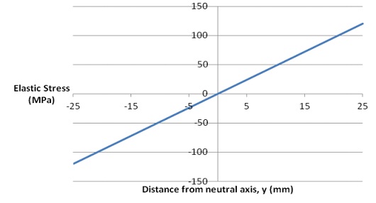
c) For a third application, the alloy is to be used in bending in a component of rectangular cross-section of breadth, b = 20mm and depth, d = 50mm. If a bending moment, M, of 1kNm is applied, the elastic stress distribution across the section, σ = My/I, is as shown in Figure. Using the elastic stress as a basis, sketch the stress distribution across the section if the alloy were to be used at an elevated temperature so that creep is occurring. NB: Only use the positive values of y for your calculations, and sketch the remainder using symmetry.
Question5.
A large hydraulic cylinder is to be treated using autofrettage, taking 80% of the wall thickness into the plastic range. The external diameter of the vessel is 200mm and the internal diameter is 100mm, so that it must be regarded as a thick cylinder. The yield stress of the material is approximately 450MPa.
(a) Calculate the internal pressure required
(i) to cause first yield
(ii) to cause yield half-way through the wall thickness
(iii) to cause yield all the way across the wall
(iv) Sketch a curve of internal pressure versus radius of yielded zone boundary for the cylinder. Comment on the factor of safety against plastic collapse associated with the target amount of yield, taking into account the assumptions inherent in the calculations.
(b) Write down the four equations which describe the hoop and radial stresses in the elastic and plastic zones of a pressurised thick cylinder. Hence, sketch the stress distribution across the wall of the cylinder indicating values of stress in MPa. Using this sketch, briefly explain the process of yielding and plastic failure of a thick-walled cylinder as the pressure increases.
Question6.
A suspended walkway in an underground cavern consists of a deck supported by three tie rods placed symmetrically about the centre as shown below:
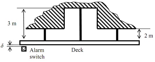
The rods are each of cross-sectional area 100mm2, are made of steel (E = 200GPa) and can be assumed to behave in an elastic-perfectly plastic fashion. The central, longer rod yields at a stress (σ y,c) of 500MPa and the outer, shorter rods yield (σ y,o) at 250MPa.
The walkway is to be designed so that an alarm is triggered when the first rods yield, but before general yield in the suspension. It is therefore important to now the downward displacement, δ, as a function of stress in the rods.
(a) Find the walkway loads and the corresponding downward displacements at which yield first occurs and at which all members have yielded.
(b) Construct the load displacement diagram and select an alarm trigger point.
(c) What is the residual displacement once a load triggering the alarm has been removed?
(d) Determine the residual displacement once a load above general yield has been removed.