Question 1.
Let us assume there is a two-terminal box. There are one resistor, one capacitor and one inductor inside the box. They can be connected in any configuration. You only have access to a DC source, signal generator, oscilloscope and one 1 Ω resistor. How can you define the connection type and numerical values of R, L and C inside the box? Explain your answers for each connection configuration in detail.
Question 2.
Let us assume a single-phase source with voltage rms of 11 kV, angle of zero and frequency of 5O Hz is connected through a line with an impedance of 0.1(1+j) ohm to an ideal transformer with the voltage ratio of 11kW400 V. The transformer secondary side is connected through a line with an impedance of 0.2(1+j) ohm to a load with an active power consumption of 1 kW and power factor of 0.7 lagging.
A) By adding a parallel device to the load, we intend to change the equivalent power factor of load and the new device to 0.95 lagging. Explain in detail what this device must be and how much its numerical value should be.
B) Calculate the current in the output of the source before and after the installation of the new device.
Question 3.
Let us assume we have a DC voltage measured in a circuit, called VA. We intend to calculate VB as
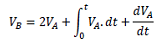
Draw an electric circuit which its input is VA and its output is VB. Then verify your circuit for any arbitrary value of VA using PSP IC E.
Question 4.
Let us assume there is a current source which generates an AC current equal to
is = sin(2Π50t) + 0.3sin(2Π150t) + 0.2sin(2Π250t) + 0.1.sin(2Π350t) + 0.05sin(2Π450t)
It Is desired that only the 50 Hz component of the current source Is passed to the rest of the circuit and all other frequency components are blocked. Now design a proper second order passive filter placed in parallel with the current source which only passes the 50 Hz component to the rest of the circuit. Verify your filter design using MATLAB or PSPICE.
Question 5.
Let us assume there is a sensitive electronic device connected to as 5V DC source. The device should be protected so that the current passing through it does not become more than 1 Ampere. A switch is made in series with the source that can disconnect the sensitive electronic device. The switch operates based on the protection circuit which we want to design. For this, let us assume a 1 ohm resistor is in series with our sensitive electronic device. The resistor's temperature is a function of its power loss as
Tempresistor = √Plossresistor
A temperature sensor is located beside the resistor which measures its temperature. Ambient temperature is not affecting this sensor. The temperature sensor output is a voltage which is equal to the temperature sensed by the sensor. Design an electric circuit which can get the output voltage of the sensor and give a zero/negative (LOW) or nonzero high (HIGH) voltage output. Once the output of the designed protection circuit becomes HIGH, the switch will disconnected the sensitive load from the source.