Q.1 Design a digital Chebyshev-II filter that satisfies the following constraints
0.7 ≤ |H(ω)| ≤ 1, for 0 ≤ ω ≤ 0.2π
|H(ω)| ≤ 0.2, for 0.6π ≤ ω ≤ π
Use Impulse Invariant transformation and verify the design. T=1.
Q.2 The frequency response of an FIR filter is given by
H(ω) = e-3jω (1+1.8cos3ω+1.2cos2ω+0.5cosω)
Determine the coefficients of the impulse response h(n) of the FIR filter.
Q.3 An FIR bandpass filter is to be designed to meet the following frequency response specifications:
Passband : 0.30-0.50 (normalized)
Transition width : 0.05 (normalized)
Stopband Deviation : 0.02
Passband Deviation : 0.01
(i) Sketch the tolerance scheme for the filter.
(ii) Express the filter bandedge frequencies, assuming a sampling frequency of 5KHz and the stopband and passband deviations in decibels.
Q.4 Explain the various FIR Filter design methods.
Q.5 Determine the Z-transforms and sketch the ROC of the following signals.
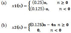
(c) x3(n) = x1(n-4)
(d) x4(n) = x1(-2n)
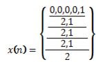
Q.6 Compute the eight-point DFT of the sequence
Using the radix-2 decimation-in time and decimation-in frequency algorithms.
Q.7 Perform the circular convolution of the following two sequences
x1(n) = {1,2,3,4} x2(n) = {5,6,7,8} using DFT - IDFT method
Q.8 Consider an FIR lattice filter with coefficients K1=0.5, K2= -0.45, K3=0.6.
(a) Find its impulse response by tracing a unit impulse input through the lattice structure
(b) Draw the equivalent direct form structure.
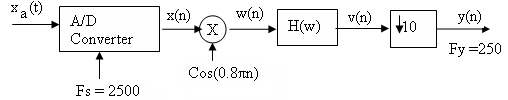
Q.9 An analog signal xa(t) is band limited to the range 150 ≤ F ≤ 750 Hz. It is used as an input to the system shown in fig below. In this system, H(w) is an ideal low pass filter with cutoff frequency Fc =250 Hz. Determine and sketch the spectra for the signal x(n), w(n), v(n) and y(n).
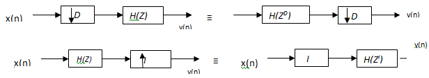
Q.10 Consider the two different ways of considering a decimator with an interpolator shown in fig.
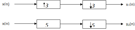
(a) Show that the outputs of the two configurations are different. Conclude the result.
(b) For what values of D and I, the systems are identical in general.
Q.11 Prove the equivalence of the two decimator and interpolator configurations shown in fig.
Q.12 Discuss briefly on each of the following concepts using diagrams.
(a) SHARC Architecture
(b) Pipelining and parallel processing
(c) MAC Unit
(d) Special instructions
(e) Data and program memory
Q.13 Consider linear prediction in noisy environment. Suppose that a signal d(n) is corrupted by noise x(n) = d(n)+w(n), where rw(k) = 0.25δ(k) and rdw(k) = 0. The signal d(n) is an AR(1) process that satisfies the difference equation d(n) = 0.25d(n-1)+v(n), where v(n) is the white noise with variance σ=1. Assume that w(n) and v(n) are uncorrelated.
(a) design a first-order FIR linear predictor w(z) = w(0)+w(1)z-1 for d(n) and find the mean square error ξ = E{[d(n+1) - d(n+1)2]}.