Assignment Outcomes:
1. Evaluate the effects of externally static - or quasi-static - applied load (axial load, torsion, bending moment, and shear) on the internal stress state of structural and machinery components.
2. Evaluate the principles of Fluid Dynamics (continuity equation, Bernoulli's equation, integral and differential forms of the conservation equations) and apply them to systems of fluid flow.
3. Demonstrate comprehension of the laws (Zero, 1st and 2nd) of Thermodynamics and how to apply them to the description of devices operating according to a thermodynamic cycle.
4. Model and solve problems involving energy balance/heat transfer of any mechanical system.
6. Demonstrate capacity to adopt a multi-technique approach to solve problems of mechanical engineering systems and document the procedures accordingly.
Detailed Project Report - Piping Systems
You will complete a full project report on a piping system for water/vapour transport. Along the course, there will be specific instructions for you to determine / calculate / dimension a component and, when relevant, provide a 2D or 3D drawing. Calculations are to be carried out in Excel and / or Mathcad Prime. Consider providing elements such as tables, plots, etc, whenever convenient for the solution of a problem.
Assignment Task: Students are required to produce a detailed project report on a specified engineering project, with its subsystems. There are multiple tasks in a project, each requiring expertise from the subjects covered along the course of the module. The report, then, is gradually completed, from early stages to its final submission. (Equivalent wording: 4500 words).
Project Report Task 01: Torsion
A member of your engineering team asked if a vertical stretch of an in-service pipe transporting hot pressurized water would be subject to torsion. The pipeline is installed on a platform, a few hundreds of metres above the sea. Provide an answer to the query, elaborating on what mechanical loads this vertical pipe may be subject to. Explain how these mechanical loads are developed (what agent causes them, etc).
Using a fictional tubular cross-section whose internal radius is half the outside radius, prove that the tubular cross-section is the best geometry to resist torsion.
Choose a commercially available pipe diameter. Analyse, via Finite Elements, a stretch of a pipe whose length is eight times the chosen diameter under an externally applied torque of 1500 kN.m. Use Creo for creating the 2D drawing with the correct dimensions and the 3D for the simulation. Compare the results of the simulation with the analytical calculation.
Project Report Task 02: Pressure Vessel
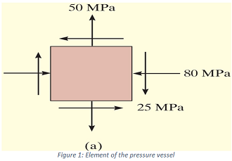
You have to design a pressure vessel. Preliminary measurements of the cylindrical vessel indicate that the normal stresses due to pressure are as shown. The state of plane stress at a point is represented by the element shown in Figure 1. Determine the state of stress at the point on another element oriented 30o clockwise.
Determine the maximum in plane shear stresses in the pressure vessel (OBS: use the applet embedded on Moodle for the calculations).
Determine the principal stresses acting on the pressure vessel (also with the applet).
Compare the result using the applet embedded on Moodle for stress transformation and the analytical solution. Are the answers the same? If not, explain with reasons.
Project Report Task 03: Pipe support
On task 1, you have specified a commercially available pipe. A linear stretch of a piping system forming a by-pass of the main line is now under your responsibility. The by-pass line is situated between two anchorage points (supports) 18 m apart from each other and will be filled with water at 4oC for testing its deflection, although the in-service conditions specify water at 20oC being transported through this stretch.
1. Prepare a technical sheet for the deflection testing, specifying:
Technical information on the pipe (relevant dimensions, material and its properties);
The free-body diagram for the by-pass line, with its loading configuration and magnitudes of the loads (caused by the self-weight of the structure and the water in the pipes).
Where to measure the deflection (and reasons why);
Reasons for the test being carried out with water at 4oC;
2. Calculate the maximum bending stress on the by-pass line and its location. OBS: you will need to calculate the second moment of inertia of area for the tubular cross section.
3. Calculate the maximum deflection of the by-pass line. ASME VIII - Section II Engineering Standard recommends the deflection to be:
5mm, for Ø3'' or less
10 mm, for Ø4'' or more
Check if the current setup of the by-pass is in agreement with the Standard. If not, recommend actions to rectify it.
4. Recommend a validation method for checking the above calculations.
Project Report Task 04: Spring support
In the previous project task, you have estimated the weight of the by-pass pipeline. The next step is devoted to the project of the support itself. The engineering team has decided to deploy a variable spring support on each anchorage point from task 3. A spring, having a free length of 407 mm and a solid length (this latter identifies the length of a spring when it is fully compressed) of 186 mm, is to be used. The initially selected spring has a constant k = 21.1 kgf/cm, but it can be replaced, if needed.
1. For one support, calculate the length of the spring with the pipeline installed on it.
2. Given that the by-pass line will also transport hot water, and knowing that the heated up pipeline displaces 2 cm vertically, determine the new load on the spring, after it has been relieved by this displacement.
3. Knowing that the relieved load is transmitted to the neighboring supports, and that the American Petroleum Institute API 570 Standard recommends a maximum of 12% of the load to be transferred, determine if pre-compression (a.k.a. pre-load) should be applied on the spring, for compliance with the standard.
4. The by-pass pipeline is connected to a pump operating at 2960 rpm. Check if the spring of the pipe support is adequate for this condition. If not, recommend a value.
5. Using the APPLET, demonstrate the effect of introducing damping into the system (play with the applet varying the value of the damping constant "c") and include an explanation, in your report, of the effect of damping on the frequency of the system and on its amplitude.
Project Report Task 05: Discharge & pipe dimensioning
Consider the following fluids and recommended speeds. On Stage 2 of the project, you have selected the pipe diameter. Now you have to determine the maximum flow the by-pass line is capable of withstanding, in m3/s. Consider the cases for water and chlorine gas.
Determine what type of flow is exhibited in both cases. What significance does this determination have on the system?
Project Report Task 06: Relief valve
An important accessory of the pipeline, especially in the case of a main line served with a by-pass, is the safety valve / relief valve. With the discharge from the last stage, you are now capable of dimensioning a relief valve.
Dimensioning a valve means to calculate, via equation 1, an orifice corresponding to an admission diameter and an output diameter, according to the API-RP 526 Standard, as indicated in table 2:
Dimension the valve for the by-pass line and choose between a safety valve and relief valve, explaining the differences between both. The by-pass line follows the same pressure specification of the main line, represented by the 2D flowchart (Figure 2 - attached) of the pressure reduction station on the back. Replicate this flowchart in an A3 drawing (use a CAD software), representing the installation of the selected valve for the by-pass line.
Project Report Task 07: Engine Cycle
In order to power the generator required to generate electricity for the industrial water usage, design a closed-system air-standard gas power cycle composed of four processes and having a minimum thermal efficiency of 30 percent. The processes may be isothermal, isobaric, isochoric, isentropic, polytropic, or pressure as a linear function of volume. Prepare an engineering report describing your design, showing the system, P-v and T-s diagrams, and sample calculations.
Explain in detail the processes mentioned above and the differences between the Otto and Diesel cycle using diagrams to buttress your points.
OBS: The construction of the document will be explained in details, so as to standardize and allow the creation of a template by the students.
OBS: The use of reference material is strongly encouraged, particularly Codes of practice and Engineering Standards from professional bodies, but not limited to these. Journal papers, books, etc. are also welcome.
Whenever you get stuck in any of your academic tasks related to the above-mentioned topic, then you can avail our Principles of Fluid Dynamics Assignment Help service for securing better academic grades.
Tags: Principles of Fluid Dynamics Assignment Help, Principles of Fluid Dynamics Homework Help, Principles of Fluid Dynamics Coursework, Mechanical Engineering Systems Assignment Help, Mechanical Engineering Systems Homework Help, Torsion Assignment Help, Torsion Homework Help, Engine Cycle Assignment Help, Engine Cycle Homework Help, Discharge & pipe dimensioning Assignment Help, Discharge & pipe dimensioning Homework Help
Attachment:- Mechanical Engineering Systems.rar