Assignment:
Q1. For the voltage conditions Z = 0.2 V when A = 0.65 V, and stating any assumptions, give the voltage range at the input B required to achieve the stated voltage conditions.
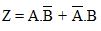
(Exclusive OR)
Q2. Implement a 7-bit even parity logic, and draw and label a diagram showing the connections among the gates used to implement this logic.
Q3. The block diagram, shown in Figure , represents a 3-bit equivalence logic function in which the output Q is high when the inputs are equivalent (that is, when simultaneously A0=B0, A1=B1 and A2=B2).
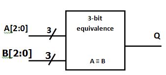
Figure. 3-bit equivalence logic function
Design and verify the equivalence function as follows:
a) For each input pair (Ai, Bi) draw a truth table to show intermediate output states (Qi) against the tabulated inputs; for example, a truth table for A0, B0 and Q0.
b) Hence, show that each intermediate output is the exclusive-NOR of the inputs.
c) Draw a truth table to show the output Q as a function of the intermediate states (Q0, Q1 and Q2).
d) Hence, show that the output (Q) is a 3-input AND function of the intermediate terms (Q0, Q1, Q2).
e) Draw and label a diagram showing the connections among the exclusive-NOR gates and the AND gate to implement the equivalence logic.
Provide complete and step by step solution for the question and show calculations and use formulas.