Assignment Task: Engineering Drawings and Documentation
Assignment Part 1: You are given a drawing. The drawing's title is "Aligned Shaft, Date: 10/01/07"
The drawing shows a shaft connected to a base at the flange. This is identified as (A) on the individual drawings for each component.
i. Calculate the total height of the assembled components.
ii. Which size bolts are used to assemble the products and what is the tap drill size for it?
iii. If the shaft is made to its biggest diameter and the hole in the base is made to its smallest diameter, what clearance will there be between the shaft and the hole?
Extract suitable information from engineering drawings and related documentation to enable a given task to be carried out.
Assignment Part 2: Study the two main components that make up the product shown in the drawing in Part 1. Identify any reasons why the product could not be made using this drawing. This may be because important information is missing.
Write down three reasons why the product could not be made because of missing or deficient information.
Explain gaps or deficiencies in the information obtained that need to be resolved to enable a given Part to be carried out.
Assignment Part 3: Where you have found that information is missing from the drawing in Part 1, identify solutions.
i. Write down the solutions you have decided on for each missing piece of information and show how these should be marked on the drawing.
ii. The two sections of shaft at (B) need to be concentric with each other, within 0.02 mm. Show on the drawing how this geometric tolerance should be representeiv.
Justify valid solutions to meet identified gaps or deficiencies with the information obtain.
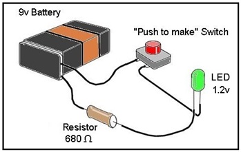
Assignment Part 4: The sketch of the electrical circuit drawing shown below needs to be converted into an electrical engineering drawing.
Research standard symbols used in electronic engineering, then produce a new circuit drawing using standard electronic component symbols.
Select other information sources to support and check engineering drawings and related documentation.
Assignment Part 5: When you are working with drawing and documentation, you need to take good care of the documents.
i. Describe the care that must be taken when handling drawings, from removal from files to return to files.
ii. Describe the importance of safe storage of documents such as job cards.
iii. Describe some security features that may be used to protect documents in a drawing office.
Specify the care and control procedures for the drawings and related documentation used when carrying out and checking own work output.
Unit: Using Computer Aided Drawing Techniques in Engineering
Assignment Task: CAD Drawing Using an Orthographic Projection Method
Assignment Part 1: Achieve the following Using CAD system:
- Show how you would start up and set up the environment of the CAD system(units, toolbars, and paper size).
- Produce a standard drawing template for an engineering drawing (border, title block and logo) as shown in lectures.
- Create a folder for information storage and retrieval with name "Mechparts" and save the template in it.
- Show the steps you would take to close down the CAD system appropriately.
Start up a CAD system, produce and save a standard drawing template and close down CAD hardware and software in the appropriate manner.
Set up a suitable electronic folder for the storage and retrieval of information.
Assignment Part 2 According to the component shown below, produce the following, taking in consideration the showing of print screens and diagrams in the report/s:
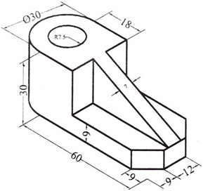
- Construct the third angle orthographic projections of the component showing the front, side and top views.
- Write a report showing the steps of storing, retrieving and printing / plotting CAD-generated or modified drawings correctly.
- Print off a copy of a diagram.
* Dimensions and hidden details should be shown.
Produce an accurate CAD drawing using an orthographic projection method.
Store, retrieve, print and plot CAD drawings correctly.
Assignment Part 3: Construct the first angle orthographic projections for the component shown below, taking in consideration that you have 25 minutes to accomplish the drawings, the print screens should show the steps with times including the starting-up and finishing times.
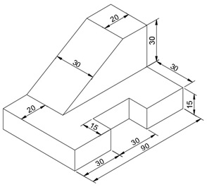
* Dimensions and hidden details should be shown.
Produce detailed and accurate drawings independently and within agreed timescales.
A number of students often seek for a reliable Engineering Drawings and Documentation Assignment Help service for completing the assignment tasks within the given time stipulation. We are the most preferred on in the industry and we ensure you that we will never let you down in any situation.
Tags: Engineering Drawings and Documentation Assignment Help, Engineering Drawings and Documentation Homework Help, Engineering Drawings and Documentation Coursework, Engineering Drawings and Documentation Solved Assignments, CAD Assignment Help, CAD Homework Help, Orthographic Projection Method Assignment Help, Orthographic Projection Method Homework Help