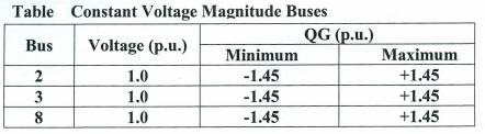
The single-line diagram of a 10-bus three-phase power system is shown in Fig. The power system has 7 generation units, 2 345-kV lines, 7 230-kV lines, and 4 transformers. The per-unit transformer leakage reactances, transmission-line series impedances, real power generation, and real and reactive loads during heavy load periods, all on a 100 MVA system base, are given on the diagram. Fixed transformer tap settings are also shown. During light load periods, the real and reactive loads (and generation) are 25% of those shown. Bus 1 is swing/slack bus. Additional data are given in Table. Transformers are solidly grounded on both sides.
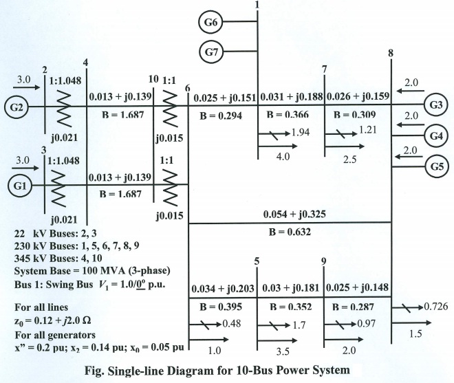
System Base Quantities: Sbase = 100 MVA (three-phase)
(a) Convert all the zero-, positive-, negative-sequence, load, and voltage data into per unit using the given system base quantities.
(b) Determine the per-unit zero-, positive-, negative-sequence bus admittance matrices.
(c) Determine the per-unit zero-, positive-, negative-sequence bus impedance matrices.
(d) Using the PowerWorld Simulator, create input data files: generator data, bus input data, line input data, and transformer input data. Bus 1 is the slack bus (swing bus)
(e) Using the PowerWorld Simulator, perform an initial power-flow solution to verify the base case system operation.
(f) Using the PowerWorld Simulator, compute the subtransients fault currents for the following:
(i) Single-line-to-ground faults at each bus.
(ii) Line-to-line faults at each bus.
(iii) Double-line-to-ground faults at each bus
Neglect prefault load currents and all losses, and assume 1.0 per-unit prefault voltage.
(g) Select a suitable circuit breaker from Table for each location shown on the single-line diagram. Each breaker should (i) have a rated voltage larger than the maximum system operating voltage, (ii) have a rated continuous current at least 30% larger than normal load current, and (iii) have a rated short short-circuit current larger than the maximum fault current for any type of fault at the bus where the breaker is located. Assume that the (X/R) ratio at each bus is less tha 15, such that the breakers are capable of interrupting the dc-offset in addition to the subtransient fault current. Circuit breaker cost should also be a factor in your selection. Do not select a breaker that interrupts 63 kA if a 40-kA or 31.50kA breaker will do the job.
Attachment:- Table-suitable circuit breaker.rar