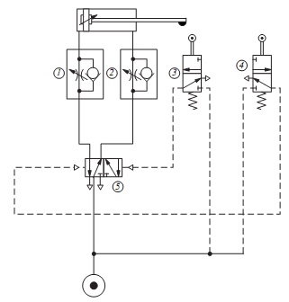
1. FIGURE shows a pneumatic circuit diagram used for air supply and exhaust in an automatic control system.
(a) Name all symbols (including pipelines) used in the system.
(b) Number the ports of each DCV.
(c) Classify the sections of the components in the circuit.
(d) State how the system works.
(e) State the functions of valves 1 and 2.
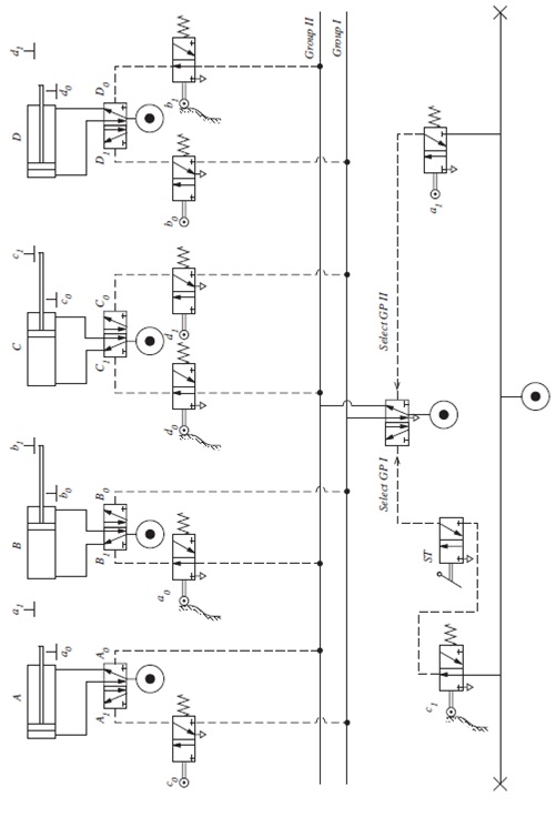
2. FIGURE shows a pneumatic circuit in which four actuators are controlled.
(a) state the sequence in which the cylinders operate on the operation of the start valve.
(b) show, with the aid of a schematic diagram, how an electronis controller could be included in the circuit to control the sequence of cylinder operations.