Piston and Flywheel
Consider the one-cylinder four-stroke engine assembly shown in Figure 1. The mass of the piston P is Mp, the mass of the connecting rod with center of mass G is ma, and the mass moment of inertia of the connecting rod about its center of mass G is IG. The dimensions of the connecting rod and the crankshaft AB are shown in Figure 1. The weight of the piston P and the connecting rod G are Wp = 0.7 lb and WG = 0.8 lb, respectively (so the masses are mp = 0.0218 slug and ma = 0.0249 slug, respectively), and the radius of gyration of the connecting rod G is kG = 2 in.
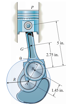
Figure 1: One-cylinder four-stroke engine consisting of: (1) piston P with mass mp, (2) connecting rod G with mass mG and mass moment of inertia IG, (3) crankshaft AB, which rotates about the fixed point A, and (4) a circular flywheel rigidly attached to the crankshaft AB, centered at A, with radius R and mass m.
The crankshaft AB rotates about the (fixed) point A, and it is rigidly attached to a circular flywheel centered at A with radius R and mass m (which is not shown in Figure 1). Neglect the mass of the crankshaft alone and assume that the flywheel is a disk, so that the mass moment of inertia of the combined crankshaft and flywheel AB about the point A is just the mass moment of inertia of the flywheel IA = mR2/2. For the purposes of this design project, we will assume that the firing of the spark plug produces a downward force F on the upper surface of the piston P that is constant (F= Fmax) for a certain angular displacement of the crankshaft and flywheel 0 ≤ θ ≤ θt and is zero (F = 0) for all other values of θ, where the angle measures the angle of rotation of the crankshaft and flywheel AB clockwise from the top-deadcenter position (TDC), as shown in Figure 1, and the angle θt is a design parameter specifying the "duration" (in terms of the rotation angle θ) over which the constant force F = Fmax is applied to the upper surface of the piston. Note that this is a great simplification of the true force F (which in reality is a function of time, and not of θ) applied to the piston after the firing of the spark plug, which is due to the burning and expanding of the gases in the combustion chamber, and is certainly not constant for any fixed range of θ. However, this simplification will suffice for this design project. During operation, the crankshaft and flywheel AB rotates in the clockwise direction, so the angular velocity of the crankshaft ωAB = θ is considered positive in the clockwise direction, corresponding to increasing θ.
In this design project, you are asked to analyze the motion of this one-cylinder four-stroke engine from the time when the spark plug fires (θ = 0, TDC) to the time when the spark plug fires again (θ = 4Π, TDC). Since this is a four-cycle engine, you will analyze the motion of the engine over two full rotations of the crankshaft AB and flywheel: (0 ≤ θ ≤ 4Π), where the angle θ is measured in radians. This takes the engine through all four cycles beginning and ending at top-dead-center (TDC) in the following order: power (0 ≤ θ ≤ Π) exhaust (0 ≤ θ ≤ 2Π), intake (0 ≤ θ ≤ 3Π), and compression (0 ≤ θ ≤ 4Π) For your design, you must specify the radius and mass of the flywheel (R and m), as well as the magnitude Fmax and "duration angle" θt so that the crankshaft AB and flywheel rotate with an angular velocity wAB = θ of at least 2500 rpm and at most 3000 rpm with a constant torque Mload = 10ft-lb applied to the crankshaft in the counter-clockwise direction. That is, the torque (load) is applied to the crankshaft against the direction of rotation. Note that the force Fmax. is applied to the piston P from 0 ≤ θ ≤ θT only during the power stroke (not during intake). Also note that the angular velocity with wAB = θ will not be constant Your design must ensure that the initial and final angular velocities of the crankshaft and flywheel at the beginning of the power stroke (θ = Π, TDC) and at the end of the compression stroke (θ = 4Π, TDC) are equal, and also that 2500 rpm < wAB = θ < 3000 rpm for 0 ≤ θ ≤ 4Π (under the specified constant applied torque of 10 ft-lb, which is the design load for the engine). This maximum rpm requirement is meant to ensure that the engine will run relatively "smoothly". The closer the maximum and minimum rpm are to each other, the more smoothly the engine will run.
Design Report:
Refer to the course syllabus for general design report requirements. In your design report, you must include the following:
(1) Include an introductory section discussing four-stroke internal combustion engines. How and when were they invented? Also discuss the various factors that you are considering in this design project: the size and mass of the flywheel, the peak force Fmax supplied by the spark plug and the "duration angle" θT over which the force is applied. What factors determine Fmax and θT realistically? What are common sizes of flywheels (mass m and radius R) on single-cylinder engines of comparable size to this one?
(2) Draw FBDs and do complete rigid-body kinematic (acceleration) and kinetic (force) analyses of all three components of the engine: the piston P, the connecting rod G, and the crankshaft/flywheel AB (since the crankshaft and flywheel are rigidly connected, they form a single rigid body). This will result in a rather large system of equations, all of which must be included in your report (typed and numbered)! These equations will involve contact forces at the pins between the crankshaft/flywheel, connecting rod, and piston, as well as the constant torque Mload applied to the crankshaft/flywheel and the force F applied to the piston P (which will be either F = Fmax for 0 ≤ θ ≤ θ or F = 0 for θT ≤ θ ≤ 4Π . The equations will also include the kinematic variables θ, θ.= ωAB, and θ.. = αAB (ωG, αG and αp which should be related to θ.= ωAB, and θ.. = αAB by kinematics).
(3) Analyze the motion of the crankshaft AB and flywheel for 0 ≤ θ ≤ 4Π (two complete rotations of the crankshaft, or all four cycles, beginning and ending at TDC), for different values of the four design parameters: R, m, θT and Fmax. (Be sure to pick realistic values for θT and Fmax) To do this, you can employ either F&A or W&E methods. To employ F&A methods, you must reduce the system of equations that you found in (2) to a single equation of motion of the form θ = f(θ,θ.,...), where θ..= wAB, and f(θ,θ.,...) is a function of θ, θ. in wAB and the parameters R, m, θT and Fmax. This equation will be a non-linear ordinary differential equation, which you can solve using a numerical analysis tool such as MATLAB to obtain the functions θ(t), θ.(t), and θ..(t). To employ W&E methods, you must balance the change in the total kinetic and potential energy of the system of rigid bodies with the nonconservative work done by the external force F and external moment Mload. In either approach, note that it will be necessary to write two separate versions of the equation of motion: (1) for 0 ≤ θ ≤ θT and (2) for θT ≤ θ ≤ 4Π. The first equation of motion will have F = Fmax and the second will have F = 0. You can then analyze these two equations of motion separately, and use the final conditions of one to supply the initial conditions of the other.