Discuss the below in detail and use APA format:
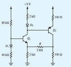
Q: Consider the circuit shown in Fig. It resembles that in Fig. 6.30 but includes other features. First, note diodes D1 and D2 are included to make design (and analysis) easier and to provide temperature compensation for the emitter-base voltages of Q1: and Q2:
Second, note resistor R, whose purpose is to provide negative feedback (more on this later in the book!). Using and VD = 0.7 V independent of current, and β=∞, find the voltages B1, VE1, VC1, VB2, VE2, and VC2, initially with R open-circuited and then with R connected. Repeat for β=100, with R open-circuited initially, then connected.