Module 1:
question Computational Kinematics
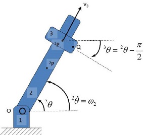
The assumptions of the system are that part 2 is rotating at a constant angular velocity of ω2 , and the ring (part 3) is sliding along part 2 at a constant velocity of 3 v .
Please state what the joints are in the system, I have worked out the constraint equations between part 3 and part 2 for you:
l3/2 [sin 2θ 2rx -3rx - cos ( 2θ)(2ry-3ry)
3θ- 2θ+ π/2=0 where irX and irY are part i’s local origin point, shown on the figure as 2P and 3P , for parts 2 and 3 respectively. l3 is the diameter of the ring.
1) Using your knowledge of computational kinematics determine the following:
• q
• C(q,t)
• {qC }
•{tC}
• Qd
If you cannot do the mathematics, then please explain what you believe is the procedure to calculate each variable.
2) Suspension set-up
This is a multi-link suspension, it is currently missing the spring and damper.
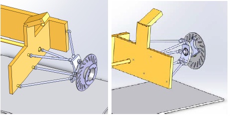
Draw the system and explain each of the components in the suspension system, please include the spring and damper in your system. Determine the correct type of joints on the multi-link suspension system. Show your Degrees of Freedom calculations. Also please explain why we need five links, what happens if you only have four links?
3) Suspension analysis
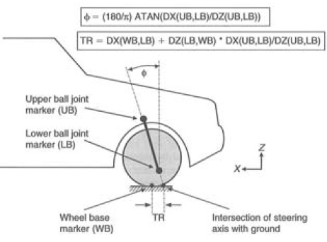
a) Calculate the castor and trail from the following data, longitudinal positive direction is the same as the X direction in the figure above. Is this suspension set-up stable? Why?
Table: Bump – rebound data
Vertical Displacement Upper ball joint Lower ball joint Wheel base marker
(mm) (Lateral, Vertical, (Lateral, Vertical, (Lateral, Vertical,
Longitudinal) mm Longitudinal) mm Longitudinal) mm
0 mm (545, 310, 300) (550, 135,300) (600, 0, 300)
100 mm (500, 410, 320) (505, 235, 290) (510, 100, 300)
0 mm (545, 310, 300) (550, 135, 300) (600, 0, 300)
-100 mm (500, 210, 290) (505, 35, 320) (510, -100, 300)
0 mm (545, 310, 300) (550, 135, 300) (600, 0, 300)
b) Explain:
• Augmented Lagrangian method
• Embedding technique
• Amalgamated formulation
c) What are the differences? What are the benefits and negatives of each method?
3) Planar dynamics
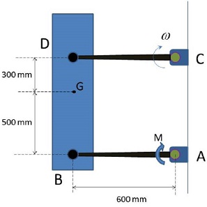
The 25-kg bar BD is attached to the two light links AB and CD and moves in the vertical plane. The lower link is subjected to a clockwise torque M=200 N.m applied through its shaft at A. If each link has an angular velocity ? ? 5 rad/sec as it passes the horizontal position, calculate the force which the upper link exerts on the bar at D at this instant. Also find the angular acceleration of the links at this position.
4) Non-linear
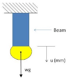
Stiffness of the Beam is given by the following equation
K= k0(u)-0.5 = N/mm
Where K0=10000 and w =1000kg.
Starting from displacement u = 0.1 as a first guess, show a Newton Raphson method solution to this problem (i.e. find and show the final tensile displacement of the beam) use a tolerance of±100N.
Now show the solution using the Modified Newton Scheme. Use a tolerance of ±100N or a maximum iteration of 4.
Finally use a Quasi-Newton method to find a solution, with a tolerance of ±100 N or a maximum iteration of 4.
Explain the difference between implicit and explicit solvers, and when to use either one or the other. Also, explain the benefits and negatives of each method. If we crush a tube at a slow speed, then which solver method would you choose? And Why?
5)Elements – Solid Shell
a) Explain what the difference is between shell elements and solid-shell elements. You may want to refer to the degrees of freedom of each.
b) Write about a scenario where you would use solid shell elements over shell elements.
6) Hyper elastic material models
a) Draw a stress-strain curve of a typical hyper-elastic material model. Explain the J parameter based on the 3rd invariant.
b) What hyper-elastic material model would you choose if you had a compressible elastomer? And why?
7) Non-linearities
a) Describe the different types of non-linearities in finite element analysis and give (draw) examples.
8) Multi-scale material modelling
a) Explain when you may need to use Multi-scale modelling, with particular reference to the material behaviour.
b) You are going to model the atomic structure of steel to show the movements and effects of dislocations, what simulation model type would you choose? What are some of the problems of linking this simulation to your macro based simulations of steel sheet forming?
9) Non-linear Material Behaviour
a) Explain what is meant by flow stress.
b) What is the associative flow rule and normality rule?
10) Contact
a) Explain the penalty method for contact. Use diagrams where possible.
b) When all else has failed, what contact method would you turn to?
11) Modelling Fibre-Matrix Composites
a) Why are fibre-matrix composites difficult to model? Please use diagrams to explain your answer.
b) Elements contain layers for modelling fibre-matrix composites, what do layers represent in an actual fibre-matrix composite?
12) Mass-scaling in explicit models
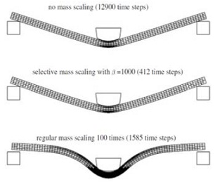
a) Explain the concept of mass-scaling. Why is it only applicable to explicit analysis?
b) With reference to the figure above, explain the problems with mass-scaling. Also explain how to determine if there is a problem with your mass-scaling simulation.
13) integration points
a) What are integration points? Why are they useful?
b) What is reduced integration?
14) Mesh refinement
a) Mesh refinement techniques need to estimate the local error for the techniques to be able update the mesh. What are some of the common error indicators used in mesh refinement?
b) Explain H-enrichment mesh refinement.
15) Multi-physics modelling
a) What is multi-physics modelling?
b) Explain the difference between direct/coupled multi-physics modelling and sequential multi-physics modelling.
c) What are some of the problems you face when coupling two or more physical models together?