Question 1
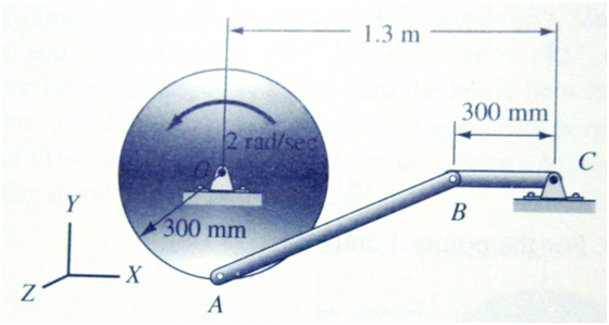
Figure Q1 shows a wheel of 300 mm radius rotating about the fixed pin O. Point A on the rim of the wheel is connected to the fixed pin C via rods AB and BC. Find:
a) the angular velocities of both rods;
b) the angular acceleration of both rods.
Question 2
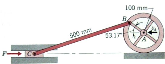
Figure Q2 shows point A on the centre of the wheel, when point A is moving to the left at 3 m/s and decelerating at 6 m/s2. The mass of the wheel is 10 kg and its radius of gyration about point A is 80 mm. The mass of the piston C and the mass of rod BC are negligible. Point B can be considerd to be on the circumference of the wheel. The wheel does not slip. For the position shown:
a) Draw the free-body diagram of the system.
b) Find the value of the force F acting on the piston C.
Question 3
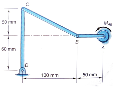
1. A crank AB is driven by a constant moment of MAB = 3 N.m, Figure Q3. The mass per unit length of each of the bar is 20 kg/m. The system starts from rest at the position shown in the figure. Using the work and energy method, determine:
(a) the angular velocity of member CD after the crank AB has revolved through an angle θ;
b) the angular velocity of member CD after the crank has completed one revolution.
Question 4
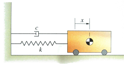
The damped spring-mass oscillator in Figure Q4 has a mas m = 2 kg, spring constant k = 8 N/m, and damping constant c = 1 N.s/m.At time t = 0, the mass is released from rest in the position x = 0.1 m.
a. Determine the position x as a function of time t.
b.Plot a graph of x = x(t) the first ten seconds of motion.