Answer all questions clearly.
A: Ideal Integrator
Question 1: Draw the basic circuit of an ideal integrator.
Question 2: The output of the ideal integrator will not saturate if the gain is not very high and if the input has no ----------- content (Fill in the blank).
Question 3: Which direction will the output swing towards (positive or negative) if the input has a slight positive DC content?
Question 4: For the ideal integrator, sketch the input and the steady state output waveforms for:
Vin is a square wave at 50% duty cycle with up and down swings of 4V each (+/- 4V). Assume Ri = 100KΩ and C = 0.2uF
The input frequency of 200 Hz.
Question 5: If the input frequency in problem (4) is doubled, what will happen to the output?
B: Practical (AC) Integrator
Question 1: Draw the basic circuit of a practical integrator.
Question 2: Why is the integrator sometimes referred to as low frequency integrator?
Question 3: If components are chosen correctly, the practical integrator is supposed to take care of the DC content by not allowing Vo to saturate. True / False? (Select one)
Question 4: Assume Ri=100KΩ, C = 0.2 uF, Rf = 500KΩ and Vin is a square wave at 60% duty cycle, up and down swings of 4V each (+/-4V) and a period of 10ms. Sketch the input and the steady state output waveforms.
Question 5: Assume Ri=100KΩ, C = 0.2 uF, Rf = 500KΩ, determine the equation for Vo(t) if Vin(t) = 2sin(ωt), Where ω = 628.31 rad/sec.
Question 6: Design an ac integrator circuit to yield the steady state output shown for the given input.
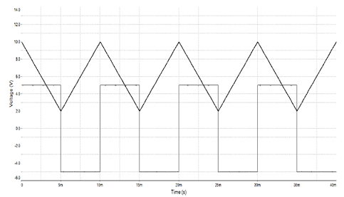
Notice: the input swings between -4.5 and 4.5 volts.
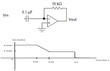
Question 7: Clearly and neatly, sketch Vout in the circuit shown below for the given input signal. Show voltage and time values.
Question 8: Assume Vin is a triangular waveform that swings between -5V to +5V ta frequency of 500Hz. Design a practical differentiator so that the output is a "proper" square-wave at 1 volt peak.
Question 9: For your result in 8, change the capacitor to 1/10th the original value and increase Rf to 3 times the original value. Run the circuit again, see if ringing occurs. If it does not, then reduce C further. Once you obtain the ringing, submit the circuit and the simulation results.
Question 10: Use LM311 to condition the output of the circuit in No. 9 above to be a pure TTL waveform (0 to 5 Volts).
Instantly Need For A Skilled Tutor From Linear Electronics Assignment Help? Your Search Ends Here At Tutorsglobe!
Tags: Linear Electronics Assignment Help, Linear Electronics Homework Help, Linear Electronics Coursework, Linear Electronics Solved Assignments, Ideal Integrator Assignment Help, Ideal Integrator Homework Help