Assignment: Flowchart and subroutines
Objectives
1. Develop a flowchart chart for a given problem statement
2. Develop a PIC assembly language program for a given flowchart
3. Develop subroutines in PIC assembly language programming
Introduction
Flowcharts are used in designing and documenting complex processes or programs. Like other types of diagrams, they help visualize what is going on and thereby help to understand a process, and perhaps also find flaws.
Symbols
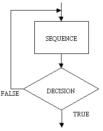
The major symbols are the DECISION (also known as selection) and the SEQUENCE (or process) symbols. The START and STOP symbols are called the terminals. The SUBPROCESS symbol is a variation on the sequence symbol. There are also connectors drawn between the symbols and you will see these used in the examples below.

Repeat loop-Note that the repeat loop has the process preceding the decision. This means that a repeat loop will always execute the process part at least once.
Subroutines
The subroutine is an important part of any computer system's architecture. A subroutine is a group of instructions that usually performs one task, it is a reusable section of the software that is stored in memory once, but used as often as necessary. This saves memory space and makes it easier to develop software.
In the PIC 16F84 the CALL instruction is used when calling a subroutine, saving the current program counter so that the Return operation knows where to restore the program counter. This is accomplished automatically (as part of the CALL instruction) pushing the return address onto the Stack, then when a Return instruction is executed, this address is popped off the stack and put into the program counter.
Pre-Lab
Provide answers to the following questions:
1. How to access SFR in Bank1 in the PIC16F84A
2. Write instruction to set pin 0, 1, 2 of PORTA as input pins and pins 3,4 of PORTA as output pins.
3. Write a subroutine called SETPORT that set the pins of PORTA according to 2 and PORTB as output port.
4. Draw a flowchart for continuously monitoring pin 0 of PORTA. If RA0=1, then continue next task, otherwise, keep reading RA0.
5. Draw a flowchart to implement the following table:
RA2 RA1 PORTB
00 0
01 1
10 2
11 3
6. Draw a flowchart to implement tasks in 3, 4, and 5 as one system.
Format your assignment according to the following formatting requirements:
1. The answer should be typed, double spaced, using Times New Roman font (size 12), with one-inch margins on all sides.
2. The response also includes a cover page containing the title of the assignment, the student's name, the course title, and the date. The cover page is not included in the required page length.
3. Also include a reference page. The Citations and references should follow APA format. The reference page is not included in the required page length.