Assignment:
Problems:
1. For the circuit to the right:
a. Analyze the circuit at t= 0+ , that is, the moment after the switch is closed.
b. Analyze the circuit as t → ∞, that is, as the circuit approaches it's equilibrium state.
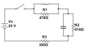
2. For the circuit to the right:
a. Analyze the circuit at t = 0+, that is, the moment after the switch is closed.
b. Analyze the circuit as t → ∞ , that is, as the circuit approaches it's equilibrium state.
c. We could consider the capacitor a "by-pass" capacitor. What does it by-pass and when?
d. We could similarly consider the inductor a "bi-pass" inductor. What does it by-pass and when?
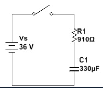
3. For the circuit to the right:
a. Determine the circuit's time constant.
b. How long does it take the capacitor to "fully" charge?
c. Write an expression for VC, VR, and I.
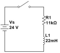
4. For the circuit to the right:
a. Determine the circuit's time constant.
b. How much current will be flowing 6 μSeconds after the switch is closed?
c. Write an expression for VL, VR, and I.
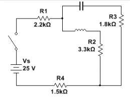
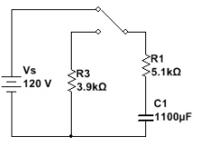
5. The switch in the circuit to the right has been in the "up" position for a long time. At, the switch is moved into the "down" position.
a. Determine VC, VR1 and VR3 at t= 0+.
b. Determine the time constant of the circuit once the switch is moved into the "down" position.
c. Write an expression for Vc, VR1, VR3 and I when the switch is in the "down" position. (Hint: The capacitor is discharging)
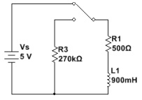
6. The switch in the circuit has been in the "up" position for a long time. At T= 0+ , the switch is moved into the "down" position.
a. Determine VL, VR1 and VR3 at T= 0+. (Hint: Treat the inductor as a current source and apply Ohm's Law)
b. What is the time constant of the circuit once the switch is moved into the "down" position?
7. Determine the specified characteristics of the waveform to the right.
a. The peak Voltage
b. The peak to peak Voltage
c. Period
d. Frequency
e. Angular Frequency
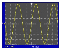
8. Write an algebraic expression for the waveform shown to the right.
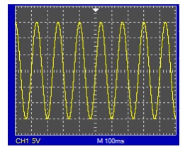
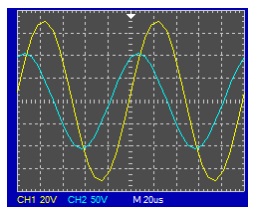
9. Use the signals to the right to:
a. Determine the phase angle separating the two signals.
b. Write an expression for the signal shown on channel 2 with the assumption that the signal on channel 1 is the reference.
10. Determine the reactance of the following components at:
ƒ = 150 hz, ƒ= 1.5 khz, and ƒ = 15 khz
a. C = 0.027 uF
b. L = 750 mH
c. What happens to the reactance of each of these components in relation to the frequency?
d. Sketch the points on a graph and extrapolate each components behavior as ƒ → 0 hz and ƒ → ∞ hz.