Design of an Urban HV Distribution Network:
Introduction:
The objective of this assignment is to do the basic planning and protection design of the sub-transmission and high voltage distribution network of a typical suburban “zone” substation. It has been designed to tie in with system studies to be done on the Power System Simulator in the Sir William Tyree (SWT) laboratory (the lab work will enable you to confirm a number of the relay settings determined as part of this assignment).
A zone substation steps “sub-transmission” voltages of 33 kV down to “high voltage distribution” voltages of 11 kV. Distribution substations on the 11 kV feeders in turn step voltages down to 415 volts for domestic and commercial use. The sub-transmission system is fed by a grid supply substation, modelled in this exercise by a single 132kV/33kV star-star transformer (but in reality would be several transformers in parallel). From this a sub-mesh of 33kV lines feed the sub-transmission network, modelled in this exercise by a single equivalent line. All impedances are shown on the diagram.
The zone substation will be constructed in two stages: initially two 25 MVA 33/11kV transformers supplying 8 outgoing 11kV feeders and ultimately three 25 MVA transformers and 15 outgoing 11kV feeders. For sake of analysis, the supply area can be assumed to be roughly circular and of uniform load (refer fig 1). Initial diversified load density (i.e. the average electrical load on the network) will be 1.0 MVA/km2 and the ultimate load density 2 MVA/km2.
On the basis of reliability, the substation always runs one of its transformers as a spare, i.e. the design capacity of a 2 transformer substation is only the rating of one and that of a 3-transformer substation is the capacity of 2 transformers. No spare capacity is provided at local distribution substations. The 11kV network is run as a “ring-main” system, where any 2 feeders can carry the load of 3 (i.e. the design capacity of the cables is based on an average load equal to 2/3 of the cable maximum rating). However, all the feeders in practice do not hit peak load at the same time (not uniformly loaded) and a “diversity factor” (DF) of 0.7 should be applied (definition is: DF = Total Substation Load/Sum of individual feeder loads, i.e. zone substation load = 0.7 * individual feeder peak loads;
conversely an individual feeder peak load = zone sub load/no of feeders/0.7). The distribution substations vary in size from “kiosk” types of 750 kVA to commercial designs of 1500 kVA capacities. All the zone and distribution transformers are 3-phase, delta-star types; delta on the HV, earthed star on the LV; the zone transformers may be earthed via an earthing reactor. The substations and network are all three-phase, 50 Hz.
The Design Task:
The design task is as follows. Analyse the system and recommend:-
• Confirm the suitability of the zone transformer impedance, and zone transformer neutral earthing impedance (if used),
• The distribution transformer impedances (for both 1500 and 750 kVA sizes),
• The 11kV cable size,
• The zone substation transformer 11 kV CT ratio, to suit the transformer’sdifferential protection scheme (allow for star-delta transformation),
• The zone substation transformer overcurrent and earth fault relay settings on HV (33kV) and LV (11kV) sides (relays ‘A’ and ‘B’),
• The sub-transmission feeder overcurrent and earth fault relay settings,
• The 11 kV feeder overcurrent and earth fault relay setting (relay ‘C’),
• The HV overcurrent relay setting on both the 1500 and 750 kVA distribution transformers (relays ‘D1’ and ‘D2’). Refer to figure 2 for the A, B, C and D relays locations.
There are both differential and overcurrent relays on each side of zone substation transformer, and overcurrent relays on each outgoing 11 kV feeder, and on the HV side of each distribution substation. The zone substation transformers have 500:5 Amp CTs on the 33kV side, and a choice of 1200:5, 1500:5 or 1800:5 on the 11kV side. The 11 kV feeders have 400:5 Amp CTs and for the distribution transformers, there is a choice of 60:5, 80:5, 100:5 or 150:5 Amp CTs. The primary rating CTs on the 11kV side of the zone substation transformers will be chosen to suit the differential protection and the overcurrent relays will have the same CT ratio. All CT secondaries (and hence also all overcurrent relays) will be 5 amps. You will have to specify the secondary current rating on the 11 kV sides of the differential relays on each zone substation transformer.
System Diagrams:
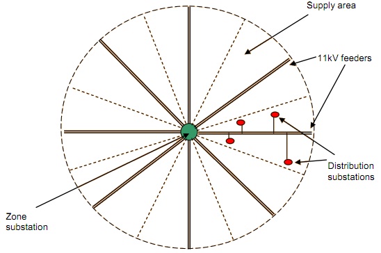
Fig: Idealised Diagram of Supply Area, for Initial (25 MVA, 8 feeder development)
Two zone substation transformers will run in parallel most times, but sometimes only one will operate. This will lower the 11 kV fault level and you need to consider this when designing the relay settings. The fault level on the 11 kV side of the zone substation must not exceed 13.1 kA for three-phase and 8 kA for single-phase faults (cable heating limits) with two transformers in parallel. The fault level on the 415V side of the distribution transformers must not exceed 15 kA for three-phase faults on the 750 kVA units and 30 kA on the 1500 kVA units. You will need to check the incoming 33 kV side of the zone substation fault levels for all three-phase and single phase to earth fault calculations (if the 3-phase fault level is OK, but the single-phase fault level too high, you may wish to consider inserting a neutral earthing impedance Zn in the zone transformer star points).
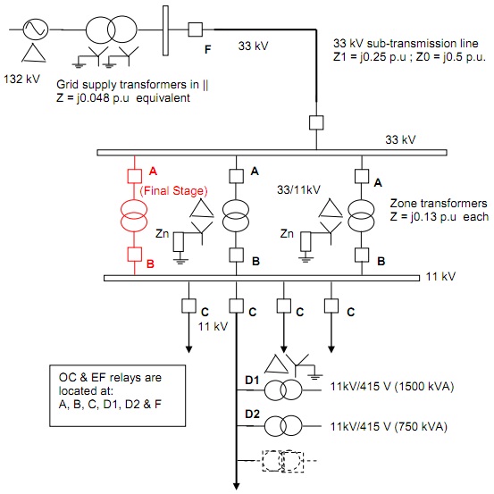
Note: All impedances are shown in per unit on 100 MVA base.
Fig: Schematic Diagram of Zone Substation, Feeders and Distribution Substations
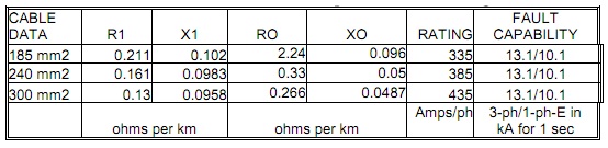
Available 11 kV (underground) 3-phase cable sizes are 185 mm, 240 mm2 and 300 mm2 aluminium. Cable impedances and ratings (in Amps) are shown in table. The maximum voltage regulation permissible on the zone substation transformers is 10% (assume purely inductive, on 0.9 lagging PF load), on the 11 kV distribution feeders it is 3% and on the distribution substation transformers 3.5%.
Table: 11kV Cable Impedances and Ratings
Standard Overcurrent Relay Characteristics:
Choose the current pick-up and time dial settings. The current pick-up must be at least 120% of normal maximum feeder load or 150% of zone or distribution transformer loading to allow for temporary overloads. In addition the setting must allow for transformer inrush current (12 times full load for 0.01 second and 6 times for 0.1 second). The distribution transformer HV setting must act as back-up for the low voltage side and be able to detect LV arcing faults of 4000 Amps phase-neutral. The earth fault pick-up settings are normally about 20% of the overcurrent, but again relays must grade correctly. Note carefully the impact of the delta-earthed star winding arrangement on all transformers, and the impact that will have on single phase to earth faults on the LV side of transformers when reflected to the HV side.
The standard IEC formula for the operating time of an overcurrent relay on “standard inverse” characteristic is:-
Time = 0.14 * TL /(I0.02 –1),
Where : Time = the operating time, in seconds
TL = the relay time dial setting,
I = the relay current, in multiples (per unit) of the relay nominal current
(in this case, the latter will be 5 amps).
A copy of the curve is attached (Fig). An Excel spreadsheet to calculate the relay times and draw curves is also available, if desired.
As part of the analysis, you will have to consider faults on or near the zone substation 11kV bus-bar and also at the extremity of the 11 kV feeders. The overcurrent relays must grade properly for these two fault conditions. When calculating faults, assume the transformers are purely inductive and ignore the R component of cable impedances.
In particular, the following grading must occur-
• Between the 11kV overcurrent and 33kV overcurrent on the zone substation transformers, for faults on the zone substation 11 kV busbar, for both one and two transformers in service (i.e. between relays ‘A’ and ‘B’),
• Between the 33kV overcurrent on the zone substation transformers, for faults on the zone substation 33kV or 11 kV busbars and the overcurrent relay at the start of the 33kV sub-transmission line (i.e. between relays ‘A’ and ‘F’),
• Between the 11kV feeder overcurrent and the 11kV overcurrent on the zone substation transformers (i.e. between relays ‘B’ and ‘C’), for faults both near the zone substation, or near the feeder extremities,
• Between the 11kV feeder overcurrent and the overcurrent on the HV side of the 11kV/415 V distribution transformers, located at both the sending end and extremity of each 11 kV distribution feeder (i.e. between relays ‘C’ and ‘D1/ D2’) for faults both near the zone substation, or near the feeder extremities.
Standard grading curves over page:
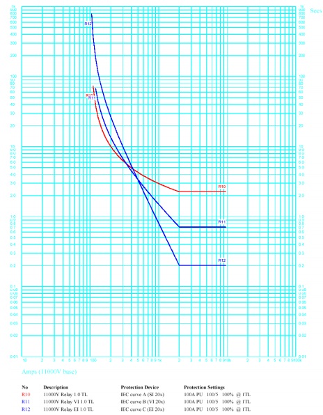
Fig: Standard Inverse, Very Inverse and Extremely Inverse Overcurrent Time-Current Characteristics for 1.0 Time Setting and 100 A current pick-up.
NB: At a given current multiple, operating time is proportional to the Time setting