Question 1) Explain Figure shown below. Identify the different elements of this diagram.
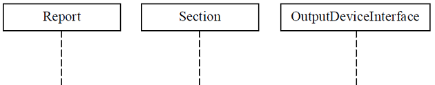
Update the diagram stepwise to show following interactions.
i) For each section, Report element retrieves the section's data using the OutputData := GetData ( ) communication sent to the Section element, and formats data using the OutputData := FormatData (OutputData) communication sent to itself.
ii) If the section's data is not summary data, Report element simply outputs the data to the OutputPrinterInterface element using the OutputNonSummaryData (OutputData) communication sent to the OutputPrinterInterface element.
iii) If the section's data is summary data, the Report element simply outputs the data to the OutputPrinterInterface element using the
OutputSummaryData (OutputData) communication sent to the OutputPrinterInterface element.
b) Describe the following modal elements of an activity diagram with suitable example.
i) Forking and joining of concurrent flow of control.
ii) Swimlanes.
Question 2)a) How do you model the context of the system using use case diagrams? Give suitable example.
b) Describe figure shown below. Identify the different elements and their relationships.
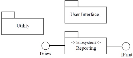
Update the diagram stepwise to show the following details in each case.
i) The User Interface package uses the IView and IPrint interfaces provided by the Reporting subsystem.
ii) The User Interface and Utility packages resides in a User Interface component.
iii) The Reporting subsystem and Utility package reside in a Reporting component.
iv) The User Interface component is deployed on a Desktop Client node.
v) The Reporting component is deployed on a Report Server node.
vi) The Desktop Client node is connected to the Report Server node, and the Report Server node is connected to a High-speed Printer node.
Question 3)a) Describe various kinds of message notations.
b) How do you represent concurrent substates and complex transitions in a state diagram? Describe with an example for each.
c) What is proxy design pattern? How do you model proxy design pattern in UML? Give suitable example.