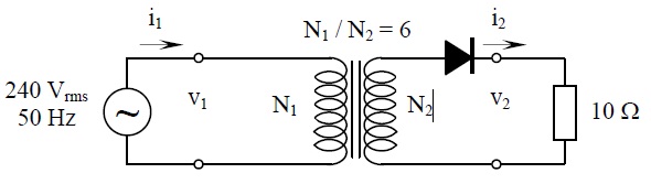
Question1)
Calculate dc voltage applied to the 10 Ω load resistor in acircuit shown below (assume diode threshold voltage is 0.7 V and bulk resistance is 0 Ω).
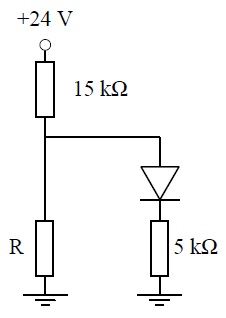
Question 2)
What value must R be in a circuit shown below to set up the diode current of 0.50 mA? (assume diode threshold voltage is 0.7 V and bulk resistance is 0 Ω).
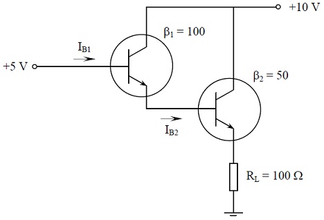
Question 3)
Calculate base current entering each transistor, IB1 and IB2, and total current gain, βtotal, for the following circuit (assume that each transistor is made from silicon and has the VBE of 0.7 V).
Question 4)
Factory has the maximum demand of 400 kW at a lagging power factor such that 600 kVAr of reactive power has to be supplied. Consider effect of adding capacitor banks in the two stages, each drawing 200 kVAr leading. Calculate power factor and apparent power in each case:
a) without capacitive load
b) with one capacitive load of 200 kVAr
c) with two capacitive loads of 200 kVAr totalling 400 kVAr
Question 5)
Using the summing operational amplifier, design 3-bit digital to analogue converter (DAC). Assume digital inputs are generated from the TTL circuit (logic 0 equal to 0 V, logic 1 equal to 5 V). Converter output must feed the speaker that has the maximum input voltage of 3.5 V. Draw the diagram of your completed circuit design and explain its operation.