Q1. Describe what is meant by the term input and output interfaces in relation to the PLCs.
Q2. State in brief what are the functions of interfaces in relation to the various types of process signal?
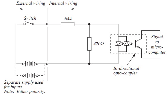
Q3. The figure shown below shows a bi-directional opto coupler input interface circuit. When a supply voltage of 20 V is applied to LED carries a current and 2 V is dropped across it. Compute the value of the LED current and the value of current via 3 kΩ resistance.
Q4. The circuit shown below is part of the interface of a relay output module. Ib is 1 mA and VCC is 9 V. The relay needs a minimum of 50 mA to energize.
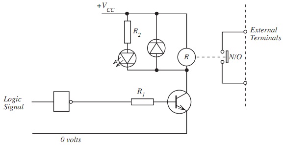
Complete the values of the suppositions listed below in order to compute:
a) Voltage across R1
b) Value of R1
c) Voltage across the relay coil
d) Voltage across R2
e) Value of R2
f) Collector of current Ic.
Assumptions:
Logic '1' = …. V
Logic '0' = …. V
Transistor forward current gain hfe = ….
LED current = 10 mA
LED voltage drop at 10 mA = …. V
Base/emitter voltage = …. V
Collector emitter voltage when transistor is on = 1 V