--%>

Prove phase shift is similar at pole and zero frequencies

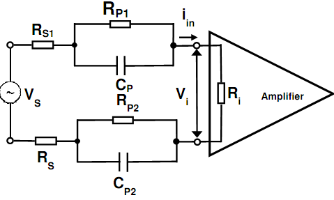
The steady state transfer function of the certain electrode amplifier interface model demonstrated below is specified as:

1564_steady state transfer function.png

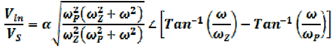
Here ωp = ωz /α and α is the attenuation factor at dc.  Prove here such the phase shift experienced through a signal at the amplifier input is similar at the pole as well as zero frequencies, ωp and ωz correspondingly.

 We suggest a useful hint to use the trigonometric identity for tan(AB).

2036_trigonometric identity.png

   Related Questions in Electrical Engineering

  • Q : Define IIR filter Define IIR filter?

    Define IIR filter? List some of the merits and de-merits of the FIR filter?

  • Q : Calculate the radius of the former of a

    The coil of a relay has 3000 turns wound upon a former having a metal core of relative permeability 8000 and is fed along with a current of 250mA. If the coil have to produce a total internal flux of 0.5Wb and the former include a length of 8cm, calculate the radius o

  • Q : Categorize the processors in the

    Categorize the processors in the embedded system?

  • Q : Handling MOS devices Specify all the

    Specify all the precautions which are to be taken while handling the MOS devices?

  • Q : Calculate the maximum thickness of the

    Excess minority carriers are injected within a thin slice of doped semiconductor of uniform cross-sectional region and are permitted to diffuse across the material. There diffusion coefficient for the material is 50cm2s-1 as well as the minority

  • Q : Power can you solve the attached

    can you solve the attached problems?? the deadline 29/4/2014 10am

  • Q : Operating mode 2 of 8051 serial port

    Specify the operating mode 2 of the 8051 serial port?

  • Q : Networking Homework Help >> Question >>

    Homework Help >> Question >> Address allocation and flow mapping assignment Any questions that are completed should be explained and given a general reason to why that strategy was used. Address allocation is already done and flow mapping is already completed. I just need Q2, Q4, Q5, Q6, Q7, Q8,

  • Q : Wavelength and Bandwidth Define: a)

    Define: a) Wavelength b) Bandwidth b) Attenuation

  • Q : Problem on combinational logic design

    Design and analysis of an IC adder built using discrete  logic and a dedicated adder using Integrated Circuits  a) Design a full adder using logic gates. In the design process show truth tables, karnaugh maps and other material used to derive the