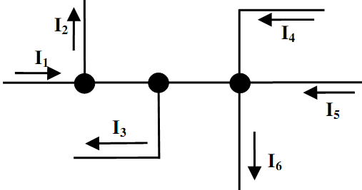
Estimate value-direction of currents applying Kirchhoff law
The currents demonstrated in figure in below have the magnitudes as given here: I1 = 1mA, I2 = 3.5mA, I3 = 2I4, I5 = 2mA, I6 = 0.5mA. By applying Kirchhoff's Current Law to the node, find out the value and direction of the currents I3 and I4.
The currents demonstrated in figure in below have the magnitudes as given here:
I1 = 1mA, I2 = 3.5mA, I3 = 2I4, I5 = 2mA, I6 = 0.5mA.
By applying Kirchhoff's Current Law to the node, find out the value and direction of the currents I3 and I4.
Explain what is meant by the term backward difference?
A bipolar diode based logic circuit is demonstrated in given figure. Establish the output voltage as the supply voltage, VCC, as well as the circuit parameters for all combinations of input logic levels along with VH = VCC and VL = 0V. Draw waveforms demonstrating the input
Explain the several functional units in the 8279?
Explain briefly the solid state circuits employed for the stator voltage control of induction motor derives.
EXPLAIN THE CHARACTERISTICS OF EMBEDDED SYSTEMS
explain the software tools in designing an embedded system
Sketch up a table demonstrating the states of conduction of each transistor within the TTL gate demonstrated below for all possible logic combinations of steady-state input states and therefore verify its logical function. Differentiate between reverse and forward mod
Explain the factors which measures the complexity of deriving the test of circuit?
Describe the attributes of the digital logic families?
Illustrates the Requirements of embedded system design process?
18,76,764
1937269 Asked
3,689
Active Tutors
1436947
Questions Answered
Start Excelling in your courses, Ask an Expert and get answers for your homework and assignments!!