--%>

Estimate minimum value of input resistance of biomedical amp

The network demonstrated in figure presents the input of a biomedical amplifier, now the input impedance is seem purely resistive, R and a capacitor, C, is used to block dc.

2417_input of a biomedical amplifier.png

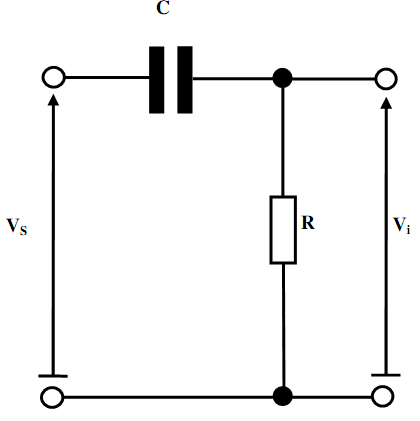
In that case the source signal is taken as a pulse of amplitude, Vm, and duration, T, described as given below:

VS(t) = Vmu(t) - Vmu(t-T)

It uses the Laplace transform method to establish an expression for the input voltage, Vi, like a function of time. 

Therefore establish the degree of the input signal undershoot, Vi, from the baseline at the ending of the pulse duration like a percentage of the pulse amplitude.

Estimate the minimum value of input resistance, R that ensures here that the undershoot does not exceed 5 percent of the pulse amplitude when the duration of the pulse is 100ms and also the capacitance C = 0.33,F.

   Related Questions in Electrical Engineering

  • Q : Find out reactance of values of

    Find out the reactance of the values of capacitor at the frequencies given below. Then find out the value of inductor in each case that will provide similar reactance as the capacitor as follows:. (a)  3.3 µF at 50Hz

  • Q : Effect of quantization over the pole

    Explain the effect of quantization over the pole location?

  • Q : Digital and Analogue Devices and

    Edexcel BTEC Levels 4 and 5 Higher Nationals in Engineering 1Unit 117: Digital and Analogue Devices andCircuitsAimThis unit aims to develop the knowledge and skills needed to design and test DC power supplysystems, operational amplifier circuits and digital elec

  • Q : Linear phase characteristic of FIR

    Explain the essential and adequate condition required for the linear phase characteristic of the FIR filter? List the well known technique for designing the linear phase FIR filter?

  • Q : Network analysis homework SIGNALS AND

    SIGNALS AND SYSTEM / BENT 2143: network analysis ASSIGNMENT Consider a rectangular pulse signal shown in Figure 1 and a system shown in F

  • Q : Counter and Frequency Counter Explain

    Explain the term Counter. Describe in detail. Write note on the Frequency Counter? Specify the major blocks which are present within the frequency counter.

  • Q : Types of branching instructions State

    State various types of the branching instructions?

  • Q : Find out impedance in form of phase and

    Find out the impedance of the network demonstrated below as considered by the voltage source, V1, while operating at a frequency of 50Hz. Illustrates this in the form of phase and magnitude. In addition, determine the current drawn from the source by the ne

  • Q : Designing the IIR filters Explain that

    Explain that why the impulse invariant method is not preferred within the design of the IIR filters rather than the low pass filter?

  • Q : Stepper motor and its uses Explain the

    Explain the term stepper motor and its uses.