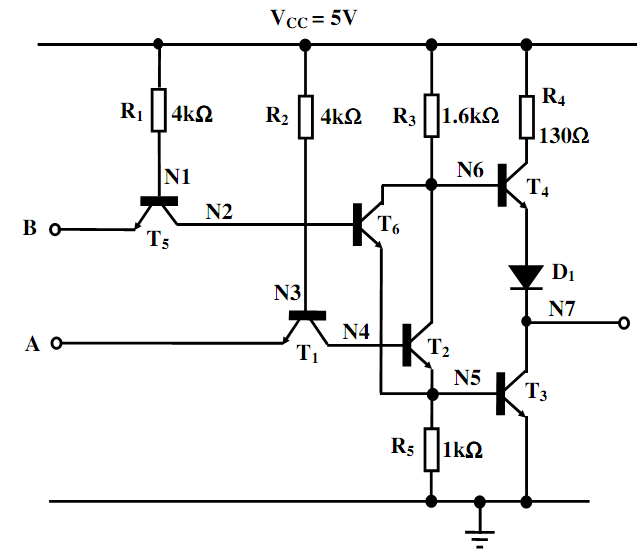
Sketch up a table demonstrating the states of conduction of each transistor within the TTL gate demonstrated below for all possible logic combinations of steady-state input states and therefore verify its logical function. Differentiate between reverse and forward modes of conduction for transistors T1 as well as T5.
Determine the voltages at each of the nodes labeled N1 to N7 within the circuit in the given steady-state conditions as follows:
(i) Both inputs low, along with Vin = 0.1Volt
(ii) In any case one input high, along with Vin = 5Volt.
Estimate therefore the power consumption in each of the above conditions.