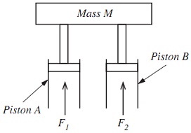
Q1. The mass M shown in figure below is to be held in position by two hydraulic pistons (A and B) that exert forces F1 and F2 (correspondingly) to the mass. The total for FT (where FT = F1 + F2) is to be controlled at a constant value.
The force F2 is not controlled; it is set at a nominal value though this might differ due to changes in the pressure of hydraulic fluid supplying piston B.
A control loop is to be employed to maintain the total applied force FT through controlling the magnitude of F1.
A) Draw a block diagram for a proportional control system (with bias) to control the FT.
B) Derive a relationship among the actual total force (FT) and:
• Force F2
• Bias B
• Controller gain C
• Desired value DV
• Feedback gain G
C) If the desired value (for FT) is 5 kN, F2 is set up nominally to 3 kN and the controller and feedback gains are 1, then find out an appropriate value for the bias.
D) If the desired value remains 5 kN, then by using the bias compute the values set out in part (c) and also find out the value of the offset produced if F2 rises to 4 kN.
-----------------------
The solution file contains MS word document with step by step solution for above problems including all steps and formulas.