ELECTRICAL SYSTEMS
TRANSFORMERS - SHORT CIRCUIT AND OPEN CIRCUIT TESTS
Objectives
1. To enhance familiarity with the measurement of electrical a.c. quantities.
2. To perform practical measurements on transformers.
3. To calculate the efficiency and voltage regulation of a loaded transformer.
- Open circuit test circuit.

V1oc is set to the transformer rated primary voltage.
Poc is the transformer core loss - the input power, in watts, with no secondary load.
Transformer frequency V1oc Poc VAoc pfoc A1oc V2oc
1
2
- Short circuit test
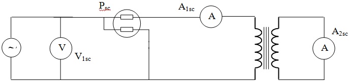
V1sc is set so that the transformer secondary current is set to its rated value.
Psc is the total transformer I2R losses when it is operating at full load.
Transformer frequency V1sc Psc VAsc Pfsc A1sc V2sc
1
2
During the open circuit tests, I2R losses are negligible and during the short circuit test transformer core losses are negligible. Thus when the transformer is operating at full load (its rated voltages and currents), the total power loss is the sum of the core loss measured during the short circuit test and the I2R loss measured during the open circuit test.
- Calculations
Perform the following calculations on the test results for both transformers.
1. The total power loss on full load.
2. The full load efficiency of the transformers at loads of 10%, 50% and 100% and power factors of 1, 0.9 and 0.7.
3. Determine the per unit voltage regulation of each transformer.
4. Draw the simplified equivalent circuit of the transformers and calculate the equivalent circuit parameters for both.