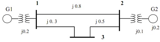
Question: A single phase line has an impedance of 8.4 + j11.2 Ω. The line feeds a load comprising of a resistor and an inductor connected in parallel as shown in figure below. The load is absorbing 30kVA at 0.6 power factor lagging. The load voltage is 1200Vrms.
Find out:
a) The values of R and X,
b) The supply current Ig and the supply voltage Vg,
c) Total real and reactive power loss in the line.
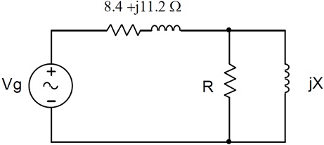
Question: A 300 km, 3-phase, 50Hz transmission line has spacing as shown in figure below. Each phase of the line comprises of a bundle of three conductors.
a) Determine the total per-phase inductance and the total per-phase shunt capacitance of the line if the conductors have diameter of 2.4cm and a GMR of 0.88cm. Suppose bundle spacing d = 0.4m.
b) Determine the percentage change of resistance, inductance and the capacitance if the line is altered by adding up one more conductors of the similar size and type to the bundle.
c) Use Matlab to check your results in (a) and ( b). Comment if the outcomes agree or not.
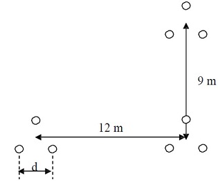
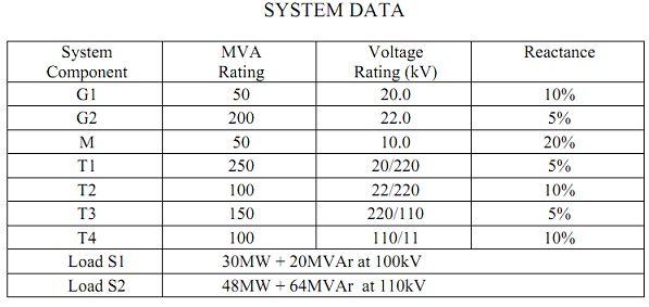
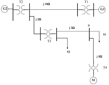
Question: The one line diagram of a simple power system is described below. The data of the system are given in the table shown below.
a) Draw the impedance diagram of the system and mark all impedances in pu on the diagram. Choose a base of 100 MVA and 20kV at generator G1.
b) Calculate the pu voltage and line to line voltage of bus B if the motor draws its rated power at its rated voltage and power factor 0.8 lagging.
Question: The 3-phase transmission line is 200km long. The line has a per phase series impedance of 0.25 + j0.45 Ω/km and shunt admittance of j7.2 μS/km. The line delivers 250MVA, at 0.6 lagging power factor and 120V to a 3-phase load.
a) Find out ABCD parameters of the line.
b) Determine the sending end voltage, sending end current, voltage regulation and the efficiency of the line.
c) Find out the capacitance per-phase of the Y–connected capacitors to adjust the power factor of the load to unity and compute the voltage regulation and the line efficiency in this case.
Question: For the 3 bus system described below all values are given in pu on a 100MVA base.
a) Use Matlab functions lfgauss and lfnewton to determine power flow solution for the system, accurate to 0.0000001pu. Compare the 2 techniques.
b) Draw the power flow diagram exhibiting voltages and powers for all busses and power losses in all lines.
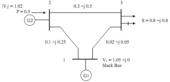
Question: The one line diagram of a simple three-bus power system is shown in the figure below. Each generator is symbolized by an emf behind the transient reactance. All impedances are expressed in per unit on a common 100 MVA base, and for simplicity, resistances are neglected. The given suppositions are made:
A) Shunt capacitances are neglected and the system is considered on no-load.
B) All generators are running at their rated voltage and rated frequency with their emfs in phase.
Find out the fault current, the bus voltages, and the line currents during the fault when:
(i) A balanced three-phase fault with fault impedance Zf = j0.02 pu occurs on bus 1;
(ii) A bolted 3-phase fault occurs on bus 3.