Task: Protection
Do all required settings to protect a given transmission line shown in figure below:
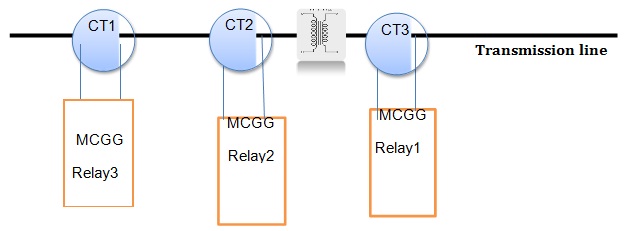
Figure: Layout of a given power system
Instructions:
1) Compute the setting of all current transformers.
2) Complete the wiring of relays following to the given instruction in MCCG manual (attached).
3) Compute and do the setting of relays using the given instructions:
a) Use the inverse curve.
b) Use relay1 as the primary protection, relay to as the backup protection and relay3 as the secondary backup protection device for potential faults on the transmission line.
c) Consider 0.2s delay as the interruption delay and 0.1s as the marginal delay between protection steps.
Task: Fault computation and interruption capacity
Consider the power system described in figure and table shown below and do the given tasks:
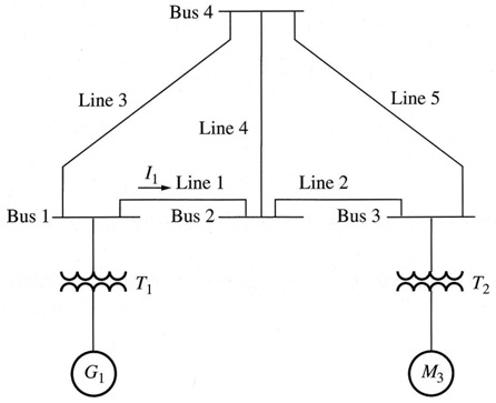
Figure: A given power system with one generators and 5 transmission lines.
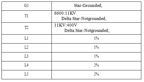
Table:
Instructions:
Consider transient impedances are 80% of nominal impedances of generators in the given system. The base power is 100MWA.
Do the given tasks:
1) Point out and label the location of all circuit breakers and disconnects in the circuit.
2) Compute the current ratings and interruption capacity of all switches.
3) Suppose a single phase ground fault takes place in Bus 3.
4) List the required protection actions, referring to the name of circuit breakers and disconnects
5) Compute the fault current.
6) Suppose a two phase fault-ground takes place in Bus 2.
7) List out the required protection actions, referring to the name of circuit breakers and disconnects.
8) Compute the fault current.