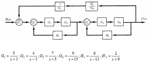
Question 1: Simplify the block diagram shown in figure below and obtain the overall transfer function. (You have to use various commands in MATLAB that will help to simplify)
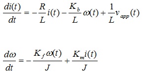
Question 2: The system model for the DC motor shown in figure below, is given by:
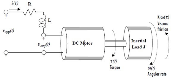
This system can be described by the following differential equations.
Assume the following constants for a typical DC motor:
L = 0.5 H
Km = 0.015
Kb = 0.015
Kf = 0.02
J = 0.02
R = 2 Ω
a) Find the transfer function of the system.
b) Plot the step response and hence determine the rise time, settling time, peak time, maximum overshoot and steady-state error.
c) Plot the impulse and ramp response of the system.
d) Sketch the Bode plot for the system
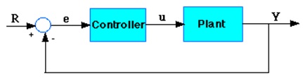
Question 3: A system’s performance can be improved by adding a controller and feedback as shown in the figuer below.The controller transfer function can be designed to obtain a desired response. Assuming the plant to be the DC motor given in Question 2, Plot the overall response of the system for the following controllers. The controller constants are to be designed based on the fast response criteria (short settling time).
a) Proportional
b) PI
c) PD
d) PID
e) Find the poles and zeros of the system in each case.
f) Comment on the obtained results.
Question 4: Plot the root-locus for a system whose open-loop transfer function is given by:
G(S) = K(s + 3)/[(s2 + 3s + 4)(s2 + 2s + 7)]
Question 5: The open-loop transfer function of a unity feedback control system is given by:
G(s) = 1/[s(s+2)(0.6s +1)]
The performance of the system is improved by using a compensator in the forward loop whose transfer function is given by:
Gc(s) = [10(10s + 1)]/[100s + 1]
a) Co-plot the step response of the uncompensated and compensated systems and comment on the results.
b) Co-plot the ramp response of the uncompensated and compensated systems and comment on the results.
c) The compensator was designed to improve the phase margin to atleast 50 degrees and the gain margin to atleast 10 dB, show by plotting the frequency response that the compensator satisfies the design criteria.
d) Sketch the poles and zeores of the uncompensated and compensated systems and comment on the stability.